General Operating Instructions
User Manual corpuls
3
36 ENG - Version 2.1 – P/N 04130.2
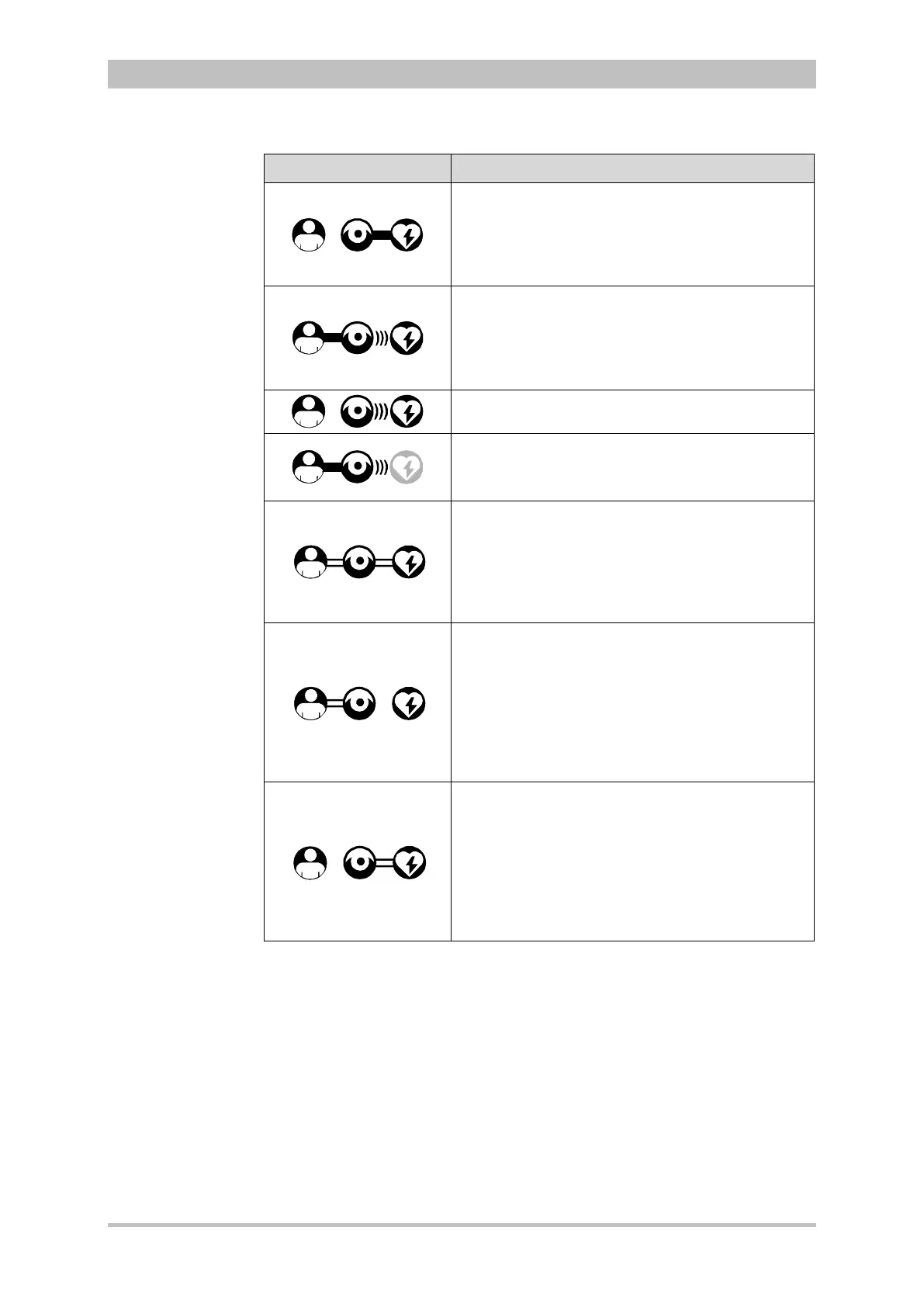
Connection status Meaning
The monitoring unit and defibrillator are connected
mechanically and communicate visually via an
infrared interface.
The patient box is disconnected mechanically, but
there is a radio connection with the patient box.
The monitoring unit and patient box are connected
mechanically and communicate visually via an
infrared interface.
The defibrillator is disconnected mechanically, but
there is a radio connection with the defibrillator.
All components have a radio connection.
The defibrillator was not switched on together with
the corpuls
3
and therefore is not available
currently.
All three components are connected mechanically
and communicate via the infrared optical
interface.
A wireless connection is not possible, because all
three components are connected with an ad-hoc-
connection.
Monitoring unit and patient box are connected
mechanically and communicate via the infrared
optical interface.
A wireless connection is not possible, because
both components are connected with an ad-hoc-
connection.
The defibrillator is disconnected; there is no
wireless connection to the defibrillator.
Monitoring unit and defibrillator are connected
mechanically and communicate via the infrared
optical interface.
A wireless connection is not possible, because
both components are connected with an ad-hoc-
connection
The patient box is disconnected; there is no
wireless connection to the patient box.
4-2 Module connection status
If the radio connection is interrupted, the modules have to be connected to each
other mechanically. The corpuls
3
switches automatically from radio
connection to infrared connection in this case.
The wave symbol or the bar symbol flashes for as long as the device is
attempting to establish a connection, but has not yet been able to do so. This
may last up to 30 sec. in some cases.
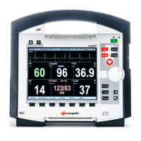
The measured parameters and the configured alarm limits are displayed in the
parameter area (Fig. 4-2, item 2) of the display.
Up to six curves of measured values of monitoring functions can be displayed in
the curve and display area (Fig. 4-2, item 3) of the display.
displa