User Manual corpuls
3
Introduction
ENG - Version 2.1 – P/N 04130.2 17
3.2.4 Defibrillator/Pacer
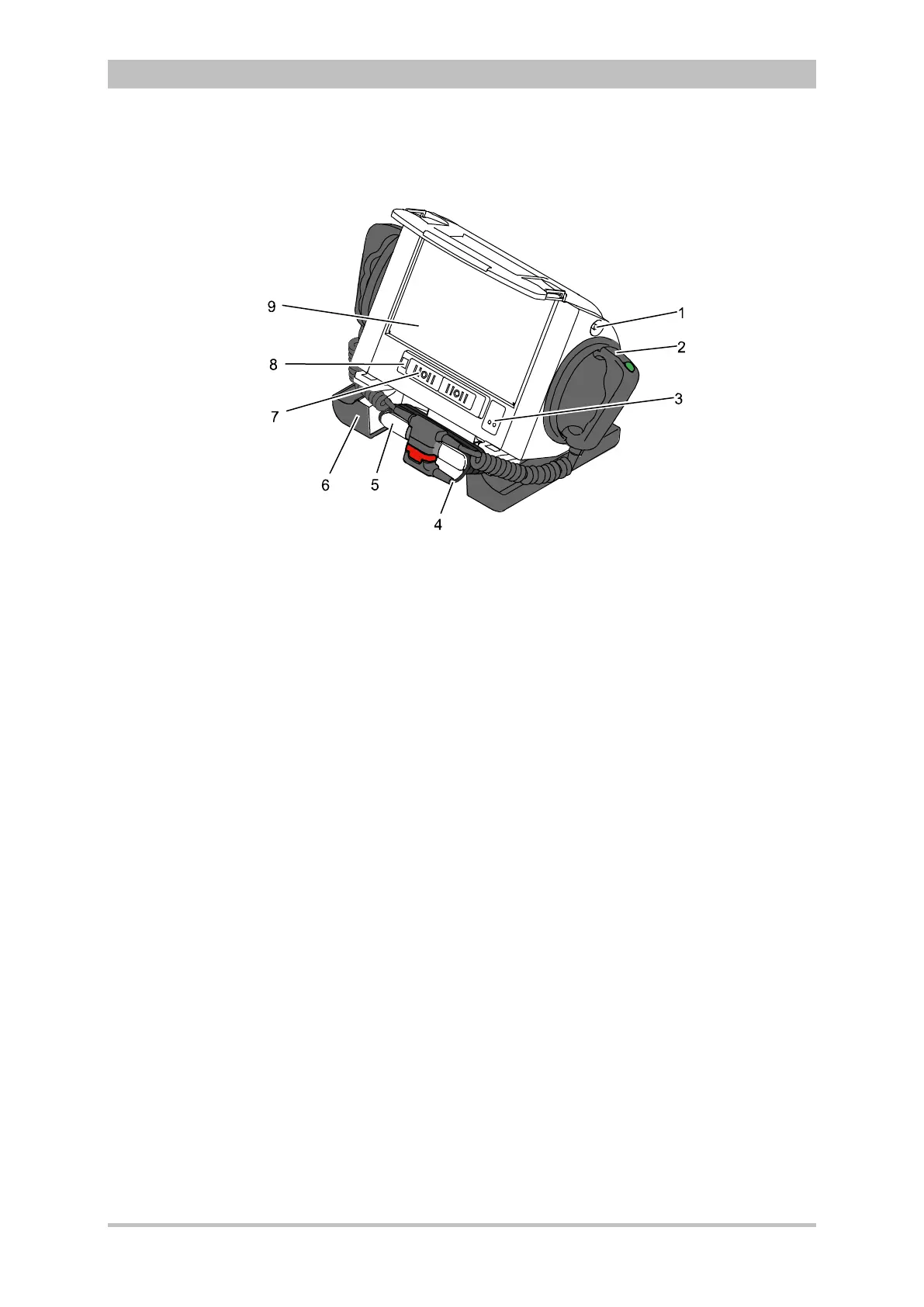
Fig. 3-11 Defibrillator/Pacer
1 Equipotential bonding pin with insulating cap
2 Shock paddle
3 On/Off key
4 Therapy master cable with plug
5 Cable socket with test contact
6 Stand and storage compartments
7 Contact element with monitoring unit
8 Infrared interface with monitoring unit
9 Compartment for corPatch electrodes
The therapy electrodes have to be connected to the therapy master cable
(item 4). The therapy master cable can be wound around the socket (item 5).
The plug can be lodged in the socket.
Equipotential bonding can be performed during clinical use with the
equipotential bonding pin (item 1). For this, the insulating cap has to be
removed.
The shock paddle marked with the green label APEX must be positioned in the
right-hand shock paddle holder to ensure that the twistproof plug connector on
the therapy master cable is correctly aligned. For guidance, identical labels for
the APEX and STERNUM shock paddle are located on the side of the
defibrillator/pacer. The plug can be lodged in the socket.
The stand (item 6) additionally serves as a storage compartment for electrode
gel and razors, etc.
The angle of the defibrillator/pacer can be tilted vertically (30°) to achieve an
optimal view of the screen during use.