Operation – Monitoring and Diagnosis
User Manual corpuls
3
98 ENG - Version 2.1 – P/N 04130.2
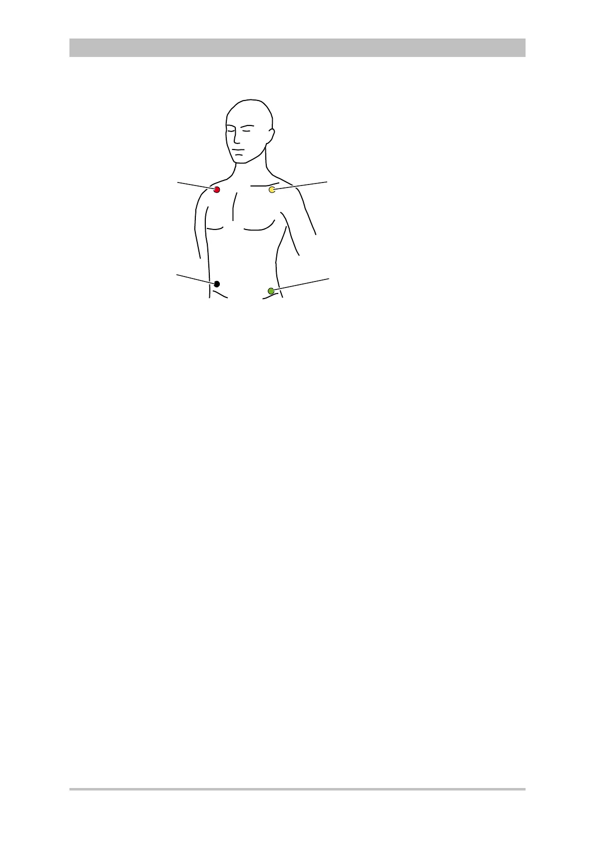
Fig. 6-2 ECG monitoring, applying the ECG electrodes (shortened form)
1 Position of the red ECG electrode
2 Position of the yellow ECG electrode
3 Position of the green ECG electrode
4 Position of the black ECG electrode
Connecting and disconnecting ECG electrodes may simulate false-positive
pacer pulses. If this occurs, the device briefly detects pacer pulses, although the
patient does not have an implanted (internal) pacer.
To check the ECG cables for functional readiness, the use ot the optionally
available ECG cable tester is recommended (see chapter 9.8 Approved
Accessories, Spare Parts and Consumables, p. 224).
6.2.4 Performing ECG Monitoring
The ECG is displayed in the following manner:
• Up to 6 leads can be displayed on the screen at the same time.
• The flashing heart symbol
♥ indicates a QRS complex.
• Identification of a QRS complex indicated by a QRS marker
can be
configured (see chapter 7.2.1 ECG Monitoring, p. 148).
• The lozenge symbol indicates pacing pulses of an implanted pacer.
• The heart rate can be displayed in a parameter field. The alarm limits can
be configured.