User Manual corpuls
3
Operation – Monitoring and Diagnosis
ENG - Version 2.1 – P/N 04130.2 105
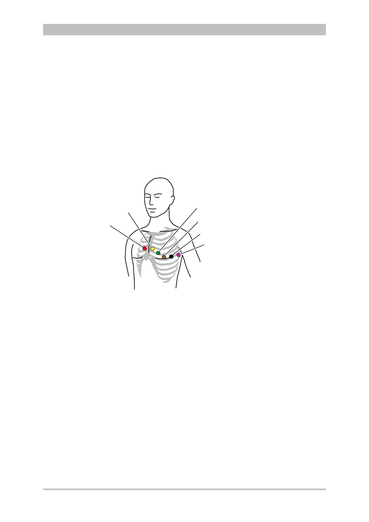
• Red V1-ECG electrode:
4
th
intercostal space, right parasternally
• Yellow V2-ECG electrode:
4
th
intercostal space, left parasternally
• Brown V4-ECG electrode:
5
th
intercostal space, left medioclavicular line
• Green V3-ECG electrode:
between V2 and V4 on the 5
th
rib
• Black V5-ECG electrode:
front left axillary line at the level of V4
• Violet V6-ECG electrode:
5
th
middle left axillary line at the level of V4
Fig. 6-8 Diagnostic ECG, applying the ECG electrodes (2)
1 Position of the red V1-ECG electrode
2 Position of the yellow V2-ECG electrode
3 Position of the green V3-ECG electrode
4 Position of the brown V4-ECG electrode
5 Position of the black V5 -ECG electrode
6 Position of the violet V6-ECG electrode
Connecting and disconnecting ECG electrodes may lead to the detection of
false-positive pacer pulses. If this occurs, the device briefly displays pacer
pulses, although the patient does not have an implanted (internal) pacer.
The ECG monitoring interfaces ECG-M and ECG-D are specified as CF
(cardiac floating). The patient connections are fully insulated and defibrillation-
proof.
The quality of the ECG recordings also depends on the ECG electrodes used:
• Only use ECG electrodes indicated in the list of approved accessories
(see chapter 9.8 Approved Accessories, Spare Parts and Consumables,
p. 224).
• Do not use ECG electrodes whose expiry date indicated on the
packaging has passed.
• Only use ECG electrodes of the same type that originate from an
identical production process (batch).