IconMaster Installation and Configuration Manual 51
Chapter 2: Installation
Table 2-8 shows default settings for the DB-9 connectors. These connector
assignments can be changed via the ICU Serial Port Configuration Settings
dialog box. For more information, see the IconMaster Functional Operations
and Configuration Manual for system software release 3.0 or higher.
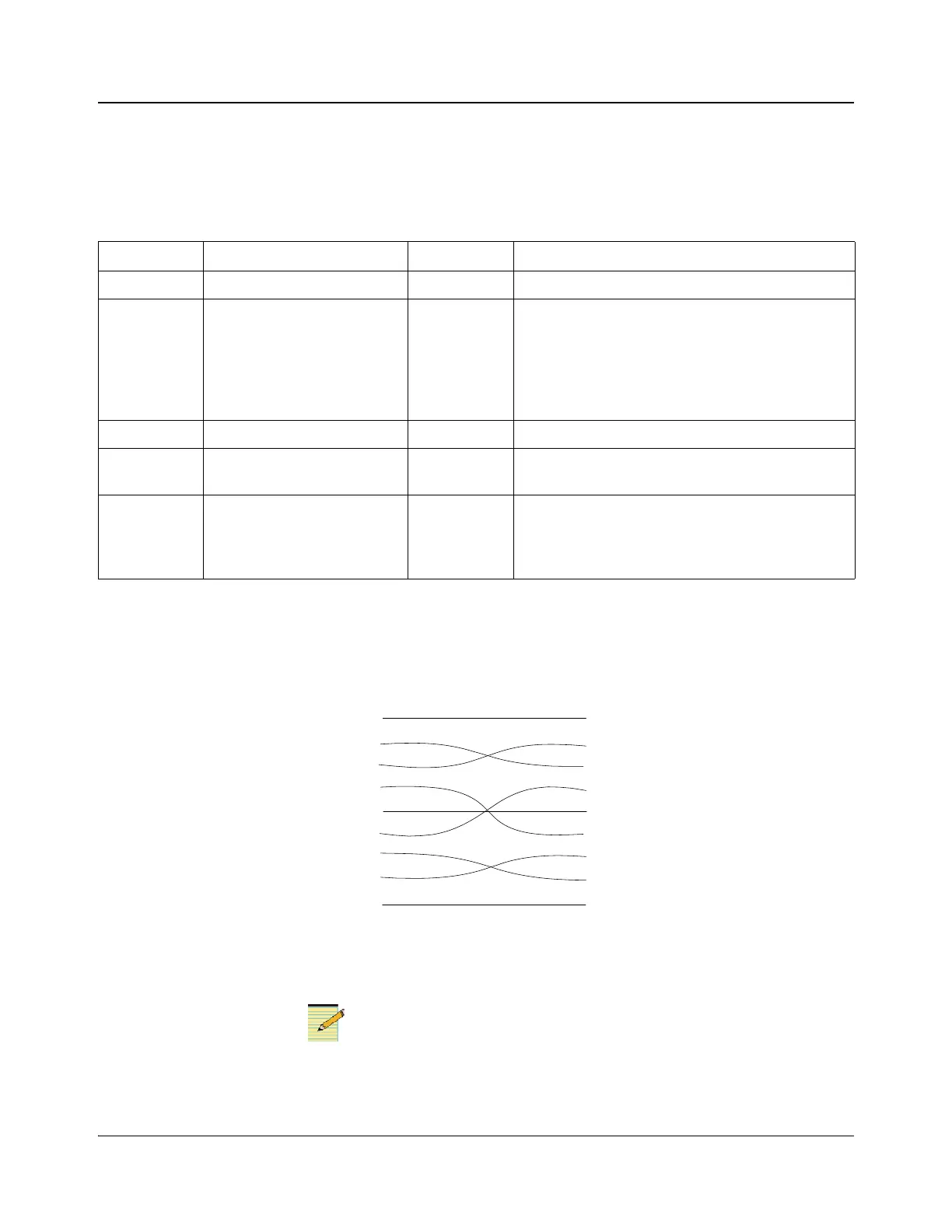
Common DB-9 Cable Arrangements Examples
Figure 2-36. RS-232 IconMaster Port E to Integrator or Panacea Pin
Connections
If re-assigned to port A, use a straight-through connection instead
of this null-modem connection.
Table 2-8. DB-9 (RS-232 and RS-422) Connector Usage
Connector Use Baud Rate Notes
RS-232-A MKE-3901 machine control 38400 See page 132 for more machine control information
RS-232/422-B MKE-3901 automation control 38400 Jumper J18 on the MKE-3901 must be set to the
required standard and jumper pack A1 on the
breakout module must be set to the same standard as
J18 (see page 31 for more jumper information)
See page 135 and page 135 for more automation
control information
RS-232/422-C Reserved 38400 Reserved for future use
RS-232-D MGI-3903 EAS 9600 Connect the EAS receiver for emergency
notification messages
RS-232/422-E MKE-3901 external router
control
38400 Jumper J17 on the MKE-3901 must be set to the
required standard and jumper pack A2 on the
breakout module must be set to the same standard as
J17 (see page 31 for more jumper information)
IconMaster
1
RxD 2
TxD 3
4
GND 5
6
7
8
9
Integrator/
Panacea
RS-232
1
2 RxD
3 TxD
4
5 GND
6
7
8
9