Appx.4
Measurement of In-circuit Components
Appx. 3 Measurement of In-circuit Components
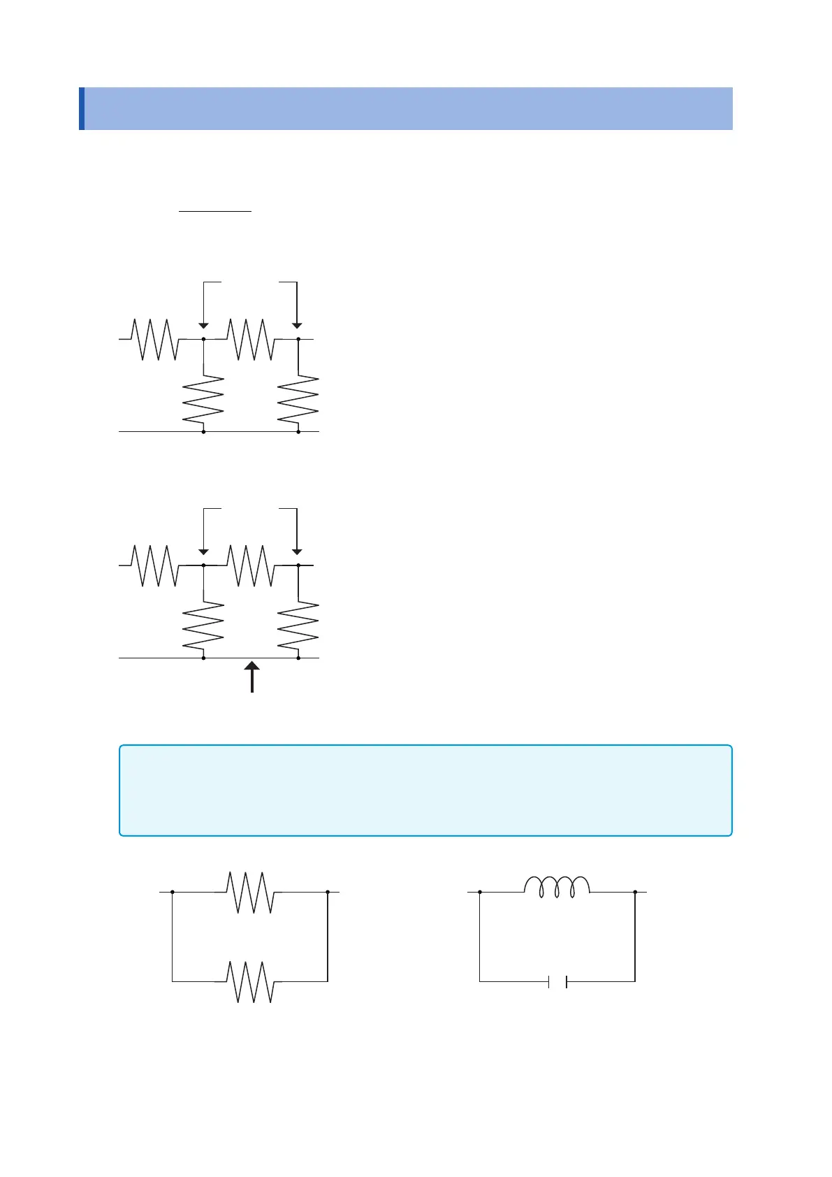
Measure an in-circuit component after providing guarding.
432
43
2
RRR
RR
++
+
•=
Referring to the following gure, when measuring a resistance
value for the resistor
R
2
, even if the tips of the two probes are
contacted against the ends of the resistor
R
2
, considering the
sum of the current owing through the resistor
R
2
and the cur-
rent owing through the resistors
R
3
and
R
4
what is obtained is
the resistance value for the parallel combination:
R
1
R
2
R
3
R
4
H L
If as shown in the next gure a guard terminal is used, the cur-
rent owing through the resistors
R
3
(not owing through
R
4
) is
absorbed by this guard terminal, so that the resistance value
for the resistor
R
2
is accurately measured.
R
1
R
2
R
3
R
4
H L
Guard terminal
• The accuracy of measurement will not be improved in cases where for example
R
2
>>
R
3
and
R
3
is close to
zero.
• As shown in the gure below, it is not possible to use this type of separation process for testing of the im-
pedance values of two resistors or other elements of identical types which are connected in parallel, or for
testing of the impedance values of a coil and a capacitor which are connected in parallel.
Two resistors in parallel
Coil and capacitor in parallel