105
Short Correction
5.3 Short Correction
With short correction, it is possible to reduce the inuence of the residual impedance of the mea-
surement cables and thereby to enhance the accuracy of measurement.
It is effective for measurement samples whose impedance is relatively low.
There are the following three methods for setting the open correction.
All correction
• Correction values are obtained for all test frequencies (p. 106).
• The range of measurement frequencies to correct can be set.
See "Correction range limitation function (to shorten the correction time)" (p. 101).
Spot correction
Correction values are obtained at the set measurement frequency only (p. 107).
Off
Short correction data becomes invalid (p. 111).
Before performing open correction
1
Review the information shown under "Check the following before performing correction:" (p. 97).
2
Follow the instructions in "5.1 Setting the Cable Length (Cable Length Correction)" (p. 98).
3
Short the measurement cable terminals.
(The shorted state varies with the measurement cable, probe, or xture being used. [
p. 2 to p. 5].
For more information, review the appropriate user manual.)
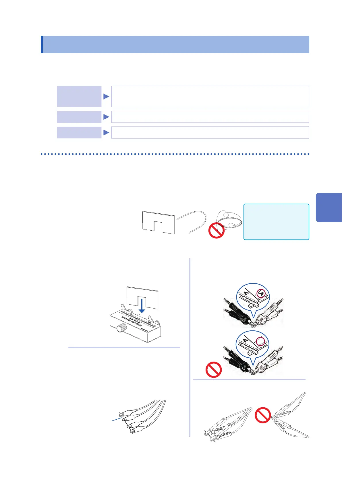
Necessary item: Shorting bar
This shorting bar is for short circuit-
ing together the ends of the test
leads. Use an object whose imped-
ance is as low as possible.
If you use a metallic wire
or the like as a shorting
bar, try to ensure that it is
as thick and short as pos-
sible.
OK
Shorting method: Short the HI and LO terminals under conditions that are as close to the mea-
surement conditions as possible.
H
POT
H
POT
H
CUR
H
CUR
OK
OK
OK
(When using a xture)
In order to keep external inuences as low as
possible, be sure to thrust the shorting bar in
all the way.
(When using optional L2000)
Short-circuit the tips with the V marks on the
clips aligned as shown in the diagram.
OK
L
POT
L
POT
L
CUR
L
CUR
(When using the optional 9140-10)
Clip both clamps onto a shorting bar as
shown.
(When using optional 9500-10)
Pinch the clips onto a short metallic wire in
the order of H
CUR
, H
POT
, L
POT
, and LCUR so
that all the terminals are shorted.
Red (HIGH)
Black (LOW)
Metallic wire
After completing the above procedure, perform short correction. See "All correction" (p. 106), and
"Spot correction" (p. 107).
5
Error Correction