168
External Input/Output Connector and Signals
BCD mode function details
LCD mode output signals operate in two modes: judgment mode and BCD mode. In BCD mode,
measured values for the No. 1 parameter and the No. 3 parameter are output using the BCD sig-
nals.
Reference: "Outputting measured values (switching to BCD mode) *LCR mode only" (p. 184)
The BCD high-order digit and low-order digit (polarity and ERR information) can be switched with
the C1 signal.
C1
――
D4
――
D3
――
D2
――
D1
――
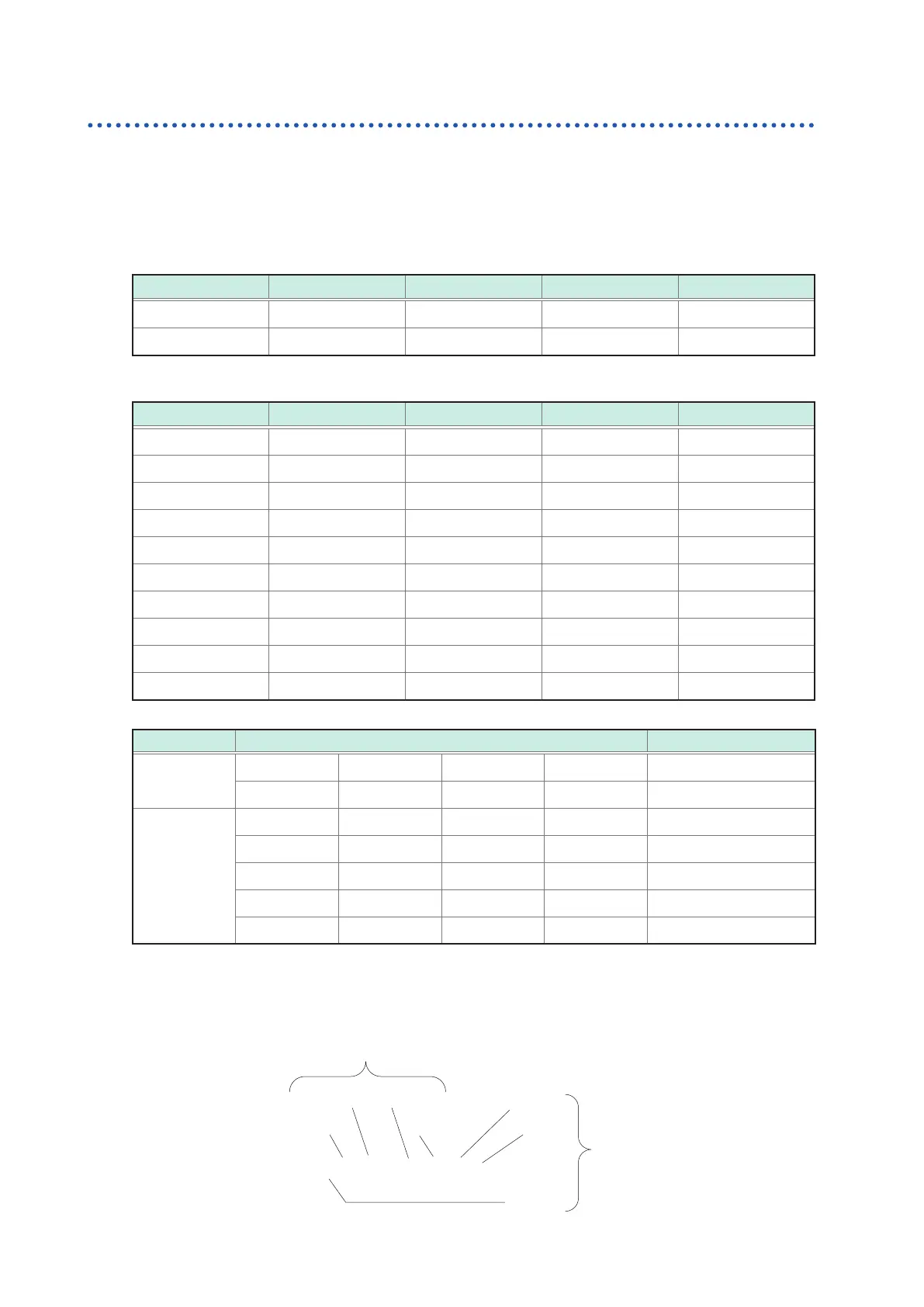
HI (high-order) No. 6 digit data No. 5 digit data No. 4 digit data No. 3 digit data
LO (low-order) No. 2 digit data No. 1 digit data Polarity ERR
Signal correspondence table
Dm-3
―― ―
Dm-2
―― ―
Dm-1
―― ―
Dm-0
―― ―
Measured value
OFF OFF OFF OFF 0
OFF OFF OFF ON 1
OFF OFF ON OFF 2
OFF OFF ON ON 3
OFF ON OFF OFF 4
OFF ON OFF ON 5
OFF ON ON OFF 6
OFF ON ON ON 7
ON OFF OFF OFF 8
ON OFF OFF ON 9
(m: 4 to 1)
Output Description
Polarity OFF OFF OFF OFF Plus
OFF OFF OFF ON Minus
ERR* OFF OFF OFF OFF Normal data
OFF OFF OFF ON OVERFLOW
OFF OFF ON OFF UNDERFLOW
OFF OFF ON ON NC (Contact error)
OFF ON OFF OFF Error
*: When other than normal data, the value 9 will be output for numerical data.
The C2 signal is used to switch between the No. 1 parameter and the No. 3 parameter.
Relationship between BCD signals and the instrument display
- 8 9 . 4 7 5 °
D4-n D1-n
D3-n D2-n
D4-n
D3-n
D2-n
C1=ON(LO)
Display