35
Connecting the Measurement Cables, Probes, or Fixture
2.4 Connecting the Measurement Cables, Probes, or
Fixture
Be sure to read the “Handling the cords, xtures, and probes” (p. 14) before connecting mea-
surement cables, probes or test xture.
Connect your measurement cables, optional Hioki probes or test xture to the measurement termi-
nals. Refer to “Options (reference: open and short correction states)” (p. 2) for details. See the
instructions provided with the xture for operating details.
Example: Hioki optional test xture
Connect directly to the measurement jacks
with the label side up, and afx with the le-
vers on the left and right.
Example: Hioki optional Model 9140-10
Connect the red plugs to the H
CUR
and H
POT
jacks, and the black plugs to the L
CUR
and L
POT
jacks.
Black
Red
Red
Black
Example: Hioki optional Model 9500-10
Connect the H
CUR
, H
POT
, L
CUR
, and L
POT
BNC plugs
to the corresponding terminals on the instru-
ment.
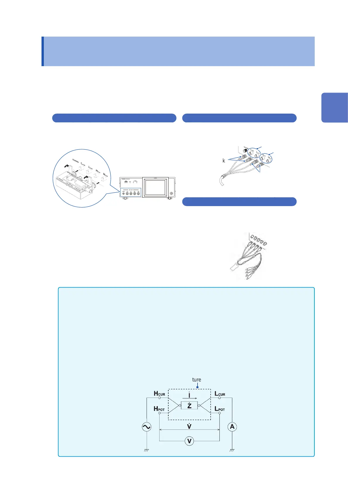
Points to pay attention to when making your own probe
• Use 50
Ω
coaxial cable for the measurement cable.
• When it ships from the factory, the instrument has been adjusted for the length of its cable. Since use
of a cable with a different capacitance value between the coaxial cable’s core wire and the shielding will
introduce a measurement error, use a cable whose capacitance value is as close as possible to that used
when adjusting the instrument prior to its shipment (1 m: 111 pF/cable; 2 m: 215 pF/cable; 4 m: 424 pF/
cable).
• Make the portion of the core wire that is exposed as short as possible.
• Connect the H
CUR
, L
CUR
, H
POT
, and L
POT
shield pairs at the measurement sample side.
(Ensure that a shield is not connected to a core wire.)
• In general, Hioki optional parts (p. 2) should be used for measurement cables and xtures. If you use a
probe yourself, it may not be able to satisfy the specications of this instrument.
• If all four terminals are disconnected, a meaningless number may be displayed on the unit.
Measurement Terminal
Conguration
Fixture
Normal mode
2
Measurement Preparations