162
External Input/Output Connector and Signals
9.1 External Input/Output Connector and Signals
Before connecting the terminals, be sure to read "Before Connecting EXT I/O" (p. 15).
This section describes the instrument’s EXT I/O connectors, compatible connectors, connector signal
assignments, input (IN) signal functionality, and output signals when errors occur.
Signal input or output is indicated as “LO (ON),” while the absence of signal input or output is indicated as “HI
(OFF).” (Please note that this usage differs in meaning from “HI” and “LO” as used for judgment results.)
Instrument connector and supported connectors
The instrument provides the following EXT I/O connector and supports use of the following types of
connectors:
Instrument side connector 37-pin D-sub female with #4-40 screws
Mating connectors • DC-37P-ULR (solder type)
• DCSP-JB37PR (pressure weld type)
Japan Aviation Electronics Industry Ltd.
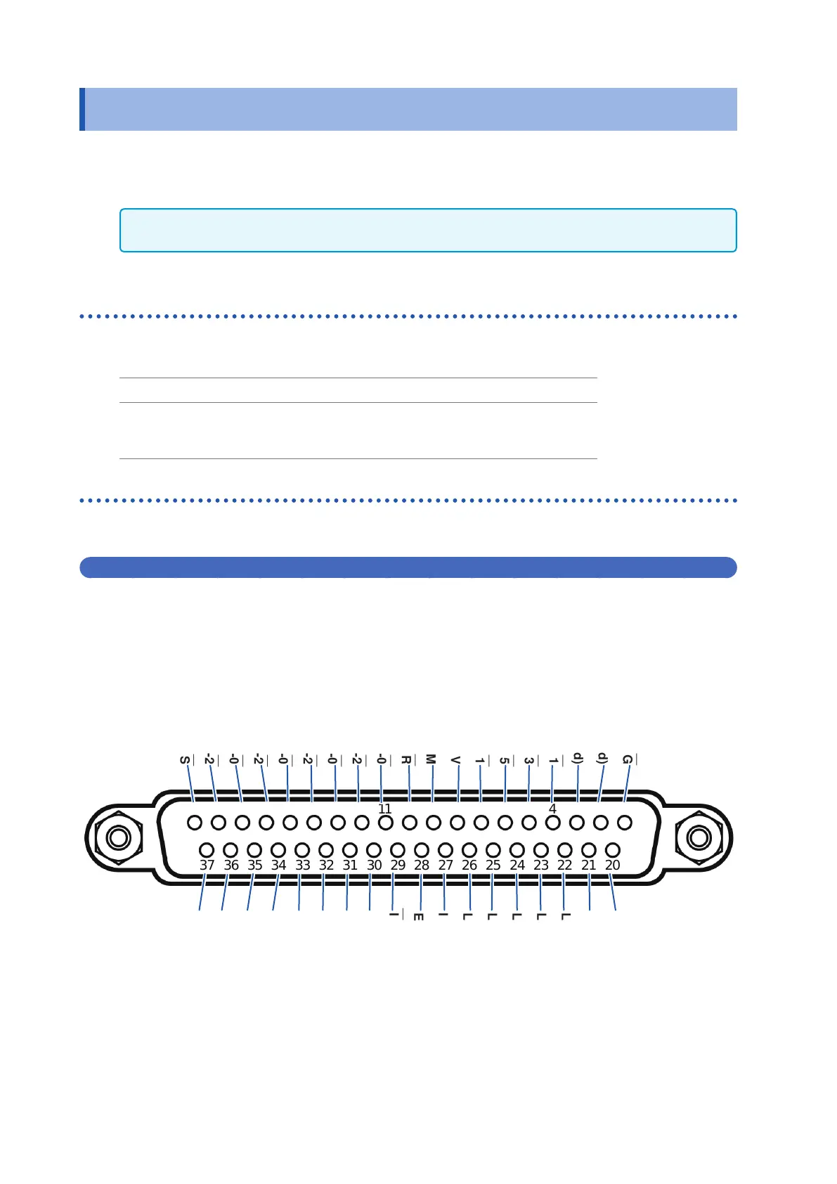
Instrument connector signal assignments
Signal assignments vary with the measurement mode.
Signal logic is 0 V to 0.9 V for LO level and 5 V to 24 V for HI level.
LCR mode (LCR) operation
2 14 36 58 79
202122232425262728293031323334353637
141516171819 10111213
TRIG
― ―――
(Unused)
(Unused)
LD1
―――
LD3
―――
LD5
―――
C1
――
ISO_5V
ISO_COM
ERR
―――
BIN1
――― ―
, PARA1-HI
――――― ――
, D1-0
―― ―
BIN3
――― ―
, PARA1-LO
――――― ――
, D1-2
―― ―
BIN5
――― ―
, PARA3-IN
―――――――
, D2-0
―― ―
BIN7
――― ―
, AND
―――
, D2-2
―― ―
BIN9
――― ―
, D3-0
―― ―
D3-2
―― ―
D4-0
―― ―
D4-2
―― ―
OUT_OF_BINS
― ― ― ― ― ――― ―
C2
――
CALIB
― ― ―――
LD0
―――
LD2
―――
LD4
―――
LD6
―――
LD_VALID
―― ―――――
ISO_COM
EOM
―――
INDEX
―― ― ― ―
BIN2
――― ―
, PARA1-IN
―――――――
D1-1
―― ―
BIN4
――― ―
, PARA3-HI
――――― ――
, D1-3
―― ―
BIN6
――― ―
, PARA3-LO
――――― ――
, D2-1
―― ―
BIN8
――― ―
, D2-3
―― ―
BIN10
――― ――
, D3-1
―― ―
D3-3
―― ―
D4-1
―― ―
D4-3
―― ―