40
Setting Display Parameters
Parameters
The following parameters are available:
Parameters Description Parameters Description
Z Impedance (
Ω
) Cs
Capacitance (F)
(Equivalent series capacitance)
Y Admittance (S) Cp
Capacitance (F)
(Equivalent parallel capacitance)
θ
Impedance phase angle (°)
*1
Q Q-factor
Rs
Effective resistance= ESR (
Ω
)
(Equivalent series resistance)
D Loss factor= tan
δ
Rp
Effective resistance (
Ω
)
(Equivalent parallel resistance)
Rdc DC resistance (
Ω
)
X Reactance (
Ω
)
σ
Conductivity (See p. 67.)
*2
G Conductance (S)
ε
Permittivity (See p. 67.)
*2
B Susceptance (S) OFF No display
Ls
Inductance (H)
(Equivalent series inductance)
Lp
Inductance (H)
(Equivalent parallel inductance)
• Parameters other than Rdc are measured using an AC signal (AC measurement).
• Rdc measures DC resistance (DC measurement).
• For more information about series equivalent circuit mode and parallel equivalent circuit mode,
see p. Appx.10.
*1: The phase angle
θ
is shown based on the impedance Z.
*2: The following message will be displayed when you select either
σ
or
ε
as a parameter: “Please set the
area and length of DUT.” Touch the EXIT key to clear the message.
To perform DC measurement (DC resistance measurement)
When Rdc is set as a parameter, you can measure the DC resistance Rdc.
For more information about measurement condition settings, see "3.4 Setting Measurement Condi-
tions (basic settings)" (p. 43).
When Rdc is set as a parameter along with other parameters, DC resistance is measured (DC
measurement) after other parameters are measured using an AC signal (AC measurement).
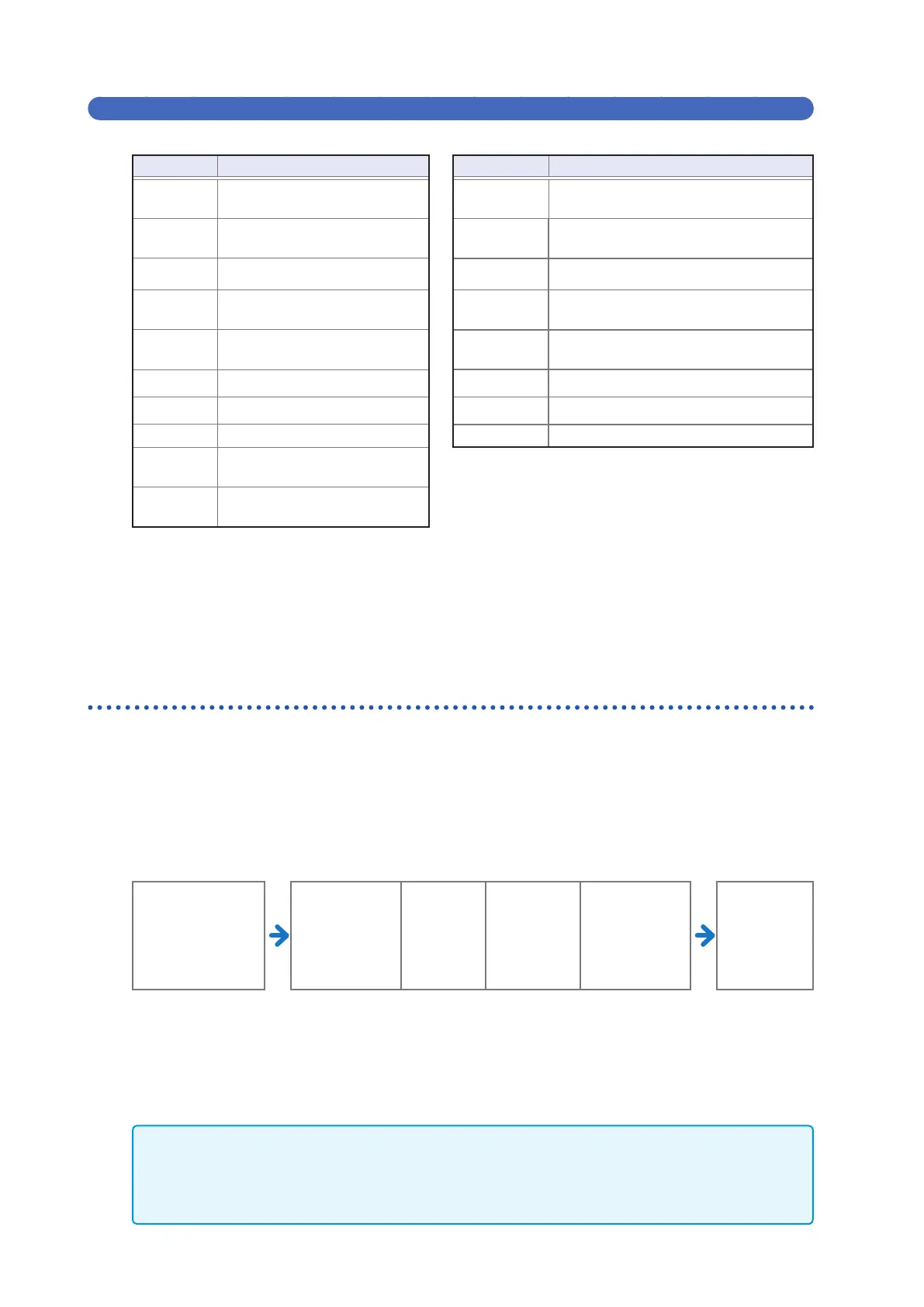
DC measurement is performed automatically using the following series of operations:
Example: When the number of average iterations is 1
Change in settings
• Change from AC
measurement to
DC measurement
• Change in range
Adjustment
delay
(default value:
0.0030 sec.)
(See shaded
area below.)
1
Offset
Measurement
DC delay
(default
value: 0 sec.)
(See shaded
value below.)
2
DC resistance
measurement
Measurement
complete
3
(Measured
value output)
1
The DC resistance is measured after setting the generated voltage to 0 V, and the result is
used as the offset value. (See "DC adjustment (reducing measurement error) (DC)" (p. 60).)
2
The DC resistance is measured after outputting 1.0 V.
3
The measurement error is reduced using the offset value, and the Rdc measured value
is output.
• When the sample is a capacitor, it may not be possible to perform DC resistance measurement normally.
• The time required until the DC signal level stabilizes differs depending on the test sample to be measured.
To facilitate more accurate measurement, observe the measurement waveform in advance and set delay
times (adjustment delay and DC delay) to allow the DC signal level to stabilize adequately. (See "Mea-
surement and data acquisition timing" (p. 65).)