Appx.10
Series Equivalent Circuit Mode and Parallel Equivalent Circuit Mode
Appx. 7 Series Equivalent Circuit Mode and Parallel
Equivalent Circuit Mode
The instrument measures the current owing to the test sample and the voltage at both ends of the
test sample, and determines Z and
θ
. Other measurement items such as
L
,
C
, and
R
are calculated
from Z and
θ
.
At this time, the mode for calculation becomes series equivalent circuit mode if the resistance com-
ponents for
C
(or
L
) are assumed to be in series, and the mode becomes parallel equivalent circuit
mode if the resistance components for
C
(or
L
) are assumed to be in parallel. It is, therefore, nec-
essary to select the parameter of the correct equivalent circuit mode to reduce errors because the
calculation formula differs for series equivalent circuit mode and parallel equivalent circuit mode.
Generally, for measurement of a low impedance device (approx. less than 100
Ω
) like a large ca-
pacitance capacitor or a low inductance, a seriese quivalent circuit mode will be selected. While,
for a high impedance device (approx. more than 10 k
Ω
) like a small capacitance capacitor or a high
inductance, a parallel-equivalent circuit mode will be selected. When you are not sure about selec-
tion of circuit mode, please ask the parts maker. (ex. a impedance approx. between 100
Ω
and 10
k
Ω
)
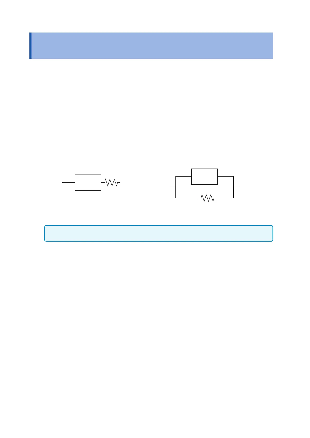
Series equivalent circuit Parallel equivalent circuit
C
(or
L
)
C
(or
L
)
Although both values can be displayed since measured values in equivalent circuit modes are calculated,
the appropriate equivalent circuit will vary with the sample.