167
External Input/Output Connector and Signals
Input (IN) signal function details
This section describes input (IN) signals.
Input (IN) sig-
nal
Detailed description
TRIG
― ―――
• When the trigger setting is the external trigger (EXT), measurement is performed once
with the falling (DOWN) or rising (UP) edge of the TRIG
― ―――
. The edge direction can be set in
the SET screen. (Initial value: Falling [DOWN])
See "Disabling the trigger input during measurement and setting the trigger input effective
edge" (p. 182). (Falling: HI→LO, rising: LO→HI)
• The TRIG signal is invalid when the trigger source is set to the internal trigger (INT).
See "Trigger (perform measurements with user-dened timing) (Common)" (p. 62).
• You can set whether to enable or disable TRIG
― ―――
input during measurement (during output
of the EOM
―――
(HI)).
"Disabling the trigger input during measurement and setting the trigger input effective
edge" (p. 182).
LD0
―――
to LD6
―――
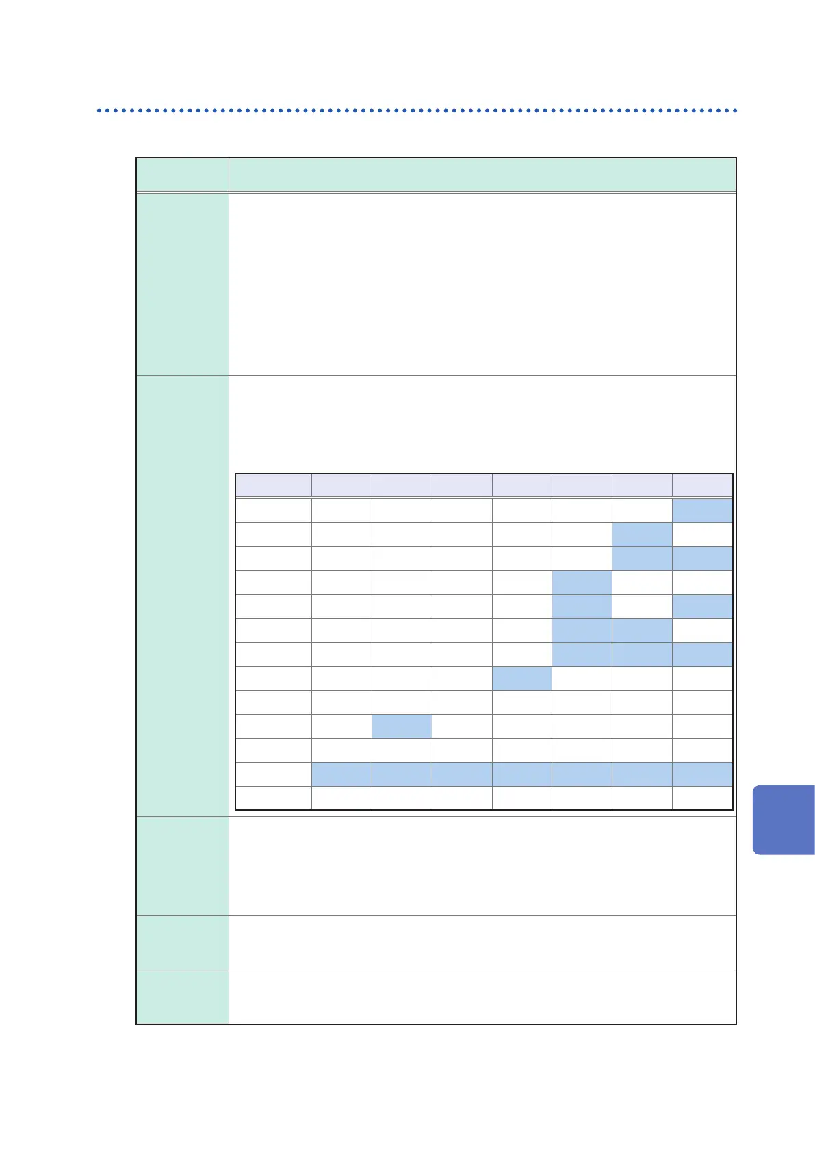
Selects the number of the panel to load.
If a trigger signal is input in external trigger mode, the selected panel is loaded and used
for measurement.
Input the panel value as a binary value to LD0
―――
to LD6
―――
.
<Example> OFF: HI (5 V to 24 V), ON: LO (0 V to 0.9 V)
Pin No. LD6
―――
LD5
―――
LD4
―――
LD3
―――
LD2
―――
LD1
―――
LD0
―――
Panel 1 OFF OFF OFF OFF OFF OFF ON
Panel 2 OFF OFF OFF OFF OFF ON OFF
Panel 3 OFF OFF OFF OFF OFF ON ON
Panel 4 OFF OFF OFF OFF ON OFF OFF
Panel 5 OFF OFF OFF OFF ON OFF ON
Panel 6 OFF OFF OFF OFF ON ON
Panel 7 OFF OFF OFF OFF ON ON ON
Panel 8 OFF OFF OFF ON OFF OFF OFF
…
Panel 32 OFF ON OFF OFF OFF OFF OFF
…
Panel 127 ON ON ON ON ON ON ON
Panel 128 OFF OFF OFF OFF OFF OFF OFF
C1
――
, C2
――
• C1
――
: Switches between the high-order digit and the low-order digit (exponent or decimal
point) in BCD mode.
OFF: High-order digit output; ON: low-order digit output (polarity, ERR)
• C2
――
: Switches between the No. 1 parameter and the No. 3 parameter in BCD mode.
OFF: No.1 parameter; ON: No. 3 parameter
• For more information about BCD mode, see "BCD mode function details" (p. 168).
LD_VALID
― ― ― ― ―――
• Input a negative logic signal from an external source when performing a panel load op-
eration.
• Maintain LO level after TRIG
― ―――
input until INDEX
―― ― ――
is output.
CALIB
― ― ―――
• When the DC adjustment function is set to OFF during DC resistance measurement,
acquires the offset value generated by the internal circuitry at the user-dened timing.
• Maintain LO level after TRIG
― ―――
input until INDEX
―― ― ――
is output.
9
External Control