Appx.1
Measurement Parameters and Calculation Formula
Appendix
Appx. 1 Measurement Parameters and Calculation
Formula
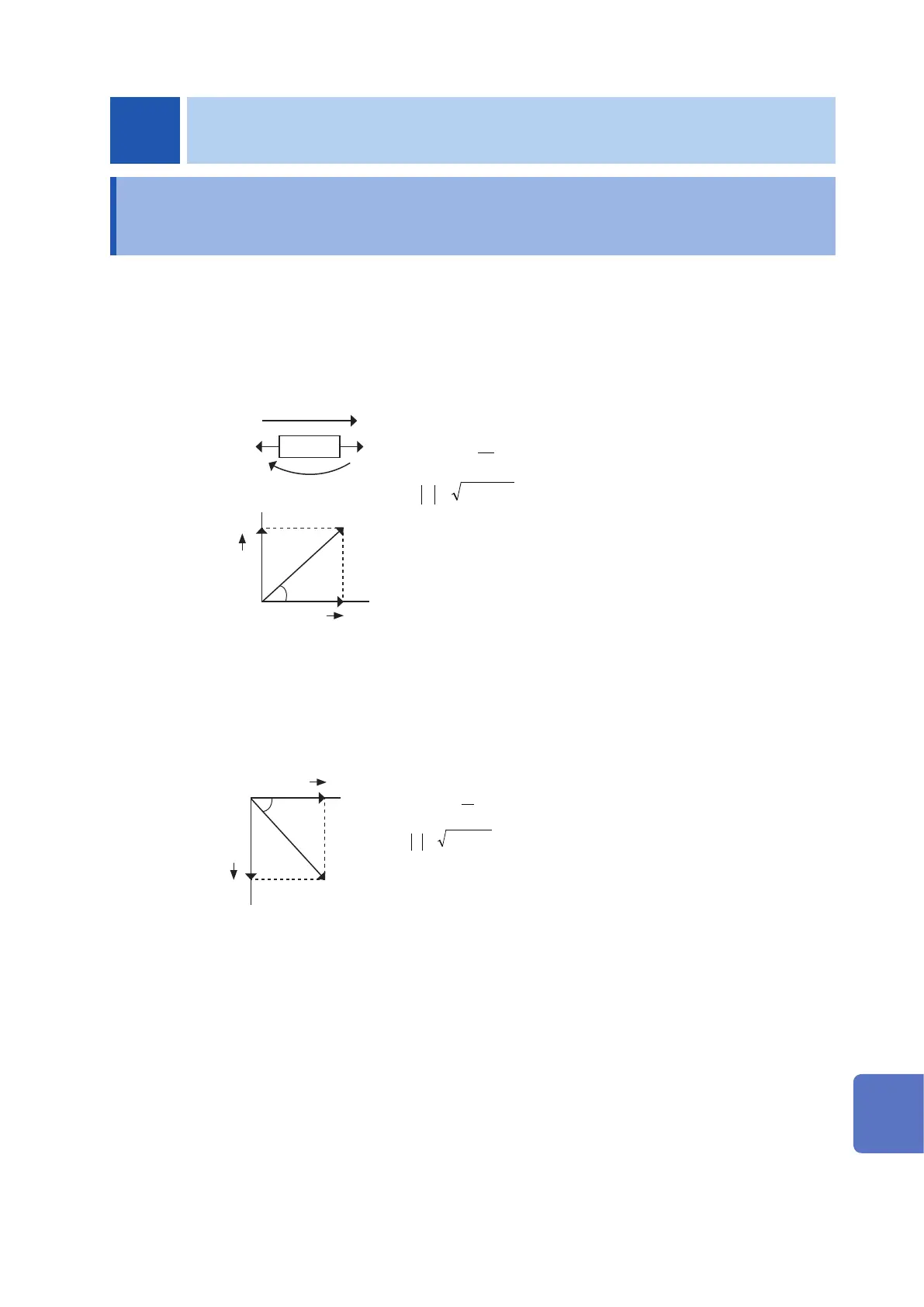
In general, impedance Z is used to evaluate the characteristics of, for example, circuit components.
Measure voltage and current vectors for circuit components relative to AC measurement frequency
signals.
The instrument uses these values to obtain the impedance
Z
and phase difference
θ
. The following
values can be obtained from impedance
Z
by rotating the impedance
Z
around the complex plane.
I
V
Z
tan
1−
=
22
XRZ +=
Z
: Impedance (
Ω
)
θ
: Phase angle (deg)
R
: Resistance (
Ω
)
X
: Reactance (
Ω
)
|
Z
| : Absolute value of impedance (
Ω
)
Imaginary
part
jX
R
Real part
θ
|Z|
Furthermore, admittance
Y
that is the reciprocal of impedance
Z
can also be used depending on
the characteristics of circuit components. As in the case of impedance
Z
, the following values can
also be obtained from admittance
Y
by rotating the admittance
Y
around the complex plane.
tan
1−
=
22
BGY +=
Imaginary
part
G
|Y|
Real part
ϕ
jB
Y
: Admittance (S)
ϕ
: Phase angle (deg) =
-θ
G
: Conductance (S)
B
: Susceptance (S)
|
Y
| : Absolute value of admittance (S)
Appendix
10
9
8
7
6
5
4
3
2
1
Appx.
索引