Appx.2
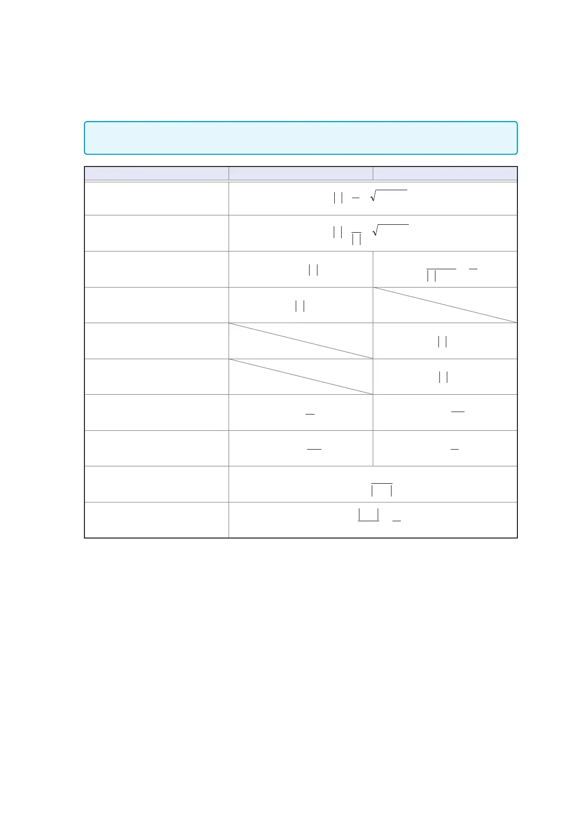
Measurement Parameters and Calculation Formula
From the voltage
V
which is applied between the terminals of the sample under test, the current
I
which ows through the test sample at this time, the phase angle
θ
between this voltage V and this
current I, and the angular velocity
ω
which corresponds to the measurement frequency.
The phase angle
θ
is shown based on the impedance
Z
. When measuring based on the admittance
Y
, the
sign of the phase angle
θ
must be reversed.
Item Series equivalent circuit mode Parallel equivalent circuit mode
Z
22
XR
Z +==
cosZESRR
S
==
==
G
1
cosY
1
R
P
Y
22
BG
Z
Y +==
cosZESRR
S
==
==
G
1
cosY
1
R
P
R
cosZESRR
S
==
==
G
cosY
R
P
φ
*
X
cosZESRR
S
==
==
G
1
cosY
1
R
P
sinZX =
G
cosZESRR
S
==
==
G
1
cosY
1
R
P
cosYG =
*
B
cosZESRR
S
==
==
G
1
cosY
1
R
P
sinYB =
*
L
cosZESRR
S
==
==
G
1
cosY
1
R
P
L
S
=
cosZESRR
S
==
==
G
1
cosY
1
R
P
L
P
−=
C
cosZESRR
S
==
==
G
1
cosY
1
R
P
C
S
−=
cosZESRR
S
==
==
G
1
cosY
1
R
P
C
P
=
D
cosZESRR
S
==
==
G
1
cosY
1
R
P
θ
sin
D =
Q
cosZESRR
S
==
==
G
1
cosY
1
R
P
==
1
sin
Q
θ
*
ϕ
: phase angle of admittance
Y
(
ϕ
=-
θ
)
Ls
,
Cs
,
Rs
: The measured values of
L
,
C
, and
R
in series equivalent circuit mode.
Lp
,
Cp
,
Rp
: The measured values of
L
,
C
, and
R
in parallel equivalent circuit mode.