170
External Input/Output Connector and Signals
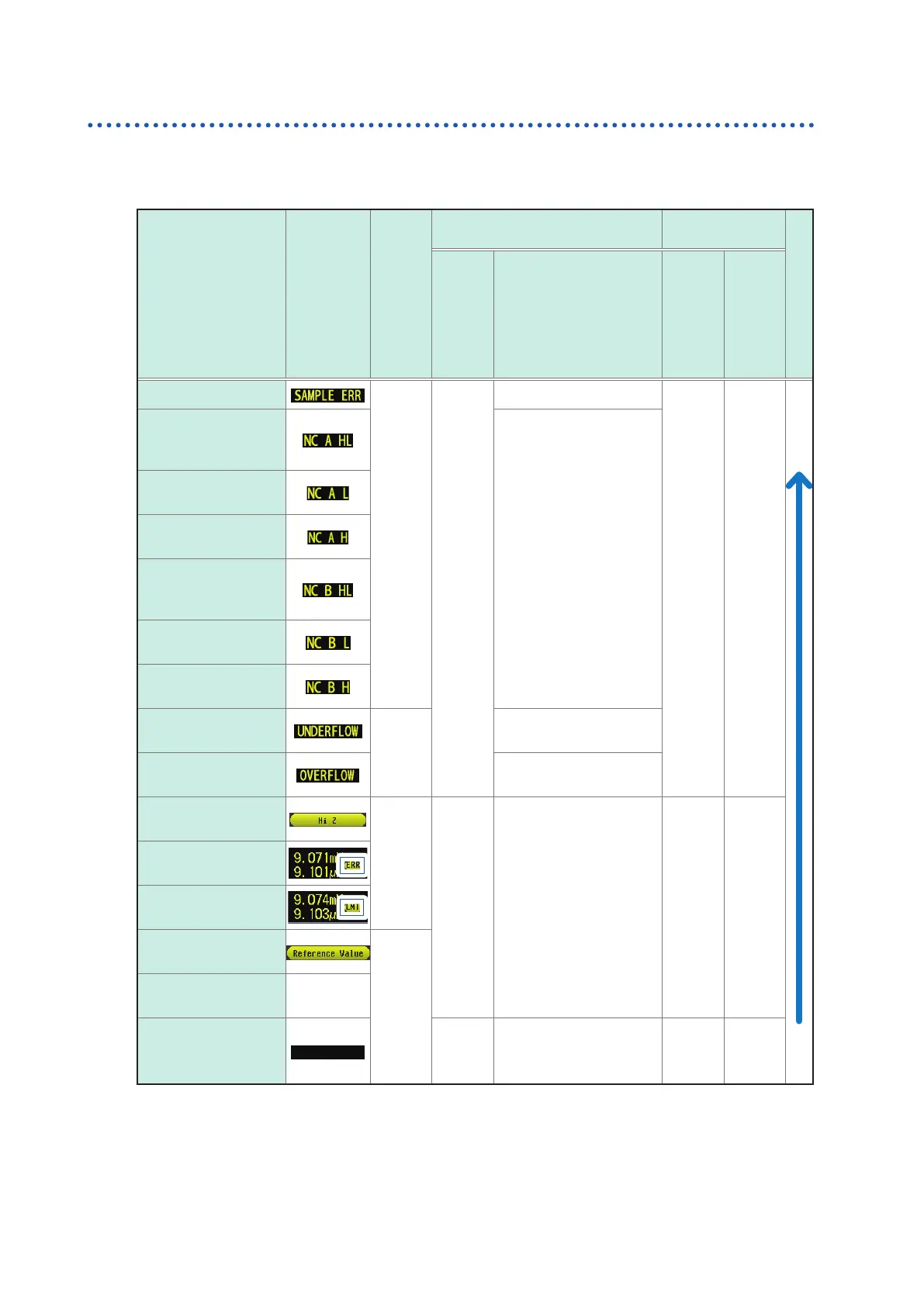
Output signals when errors occur
When an error occurs, the signals are as follows. When multiple errors occur, the signal with the
highest precedence is output.
Reference: "11.3 Error Massage and Error Display" (p. 230)
Error
Screen error display
ERR
No. 10 Pin
*1
During comparator measurement
During BIN mea-
surement
Priority Order
Logical product
and No. 14 Pin
Each Parameter
Judgment Result
Pin Nos. 11 to 13
and 30 to 32
BIN1 to BIN10
Pin
Nos. 11 to 15 and
30 to 34
OUT_OF_BINS
Pin
No. 19
Sampling error
LO
HI
HI
HI LO
High
Low
Simultaneous H and L
contact errors
(after measurement)
Pin Nos. 11 and 31
: LO
*2
(LCR mode only)
L side contact error
(after measurement)
H side contact error
(after measurement)
Simultaneous H and
L contact errors
(before measurement)
L side contact error
(before measurement)
H side contact error
(before measurement)
Underow
HI
Pin Nos. 12 and 32: LO
*2, 3
(LC
R mode only)
Overow
Pin Nos. 11 and 31
: LO
*2, 4
(LC
R mode only)
Outside of High-Z
reject limit range
LO
Normal
judgment
Normal judgment
Normal
judgment
Normal
judgment
Constant voltage/
constant current error
Voltage/current limit
value exceeded error
Outside of guaranteed
accuracy range
HI
Normal
Measured
value
No measurement after
power turned on
HI HI HI HI
*1: LO output is generated if even one error for which output changes to LO occurs.
*2: Pin numbers that change to LO level are shown.
*3: Pin Nos. 11 and 31 will be LO when the parameters are Y, Cs, G, and B. (LCR mode only)
*4: Pin Nos. 12 and 32 will be LO when the parameters are Y, Cs, G, and B. (LCR mode only)