5
Verifying Package Contents
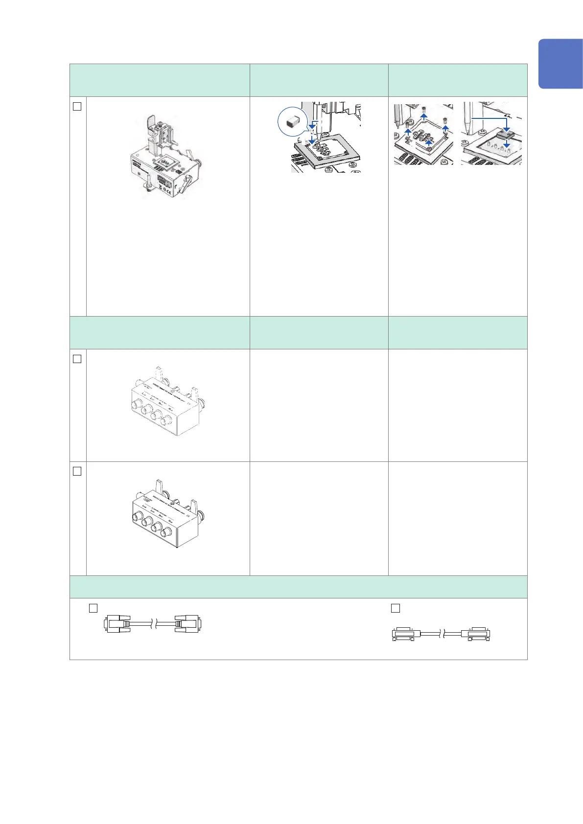
Test xture types
Open state during open
correction
Shorted state during short
correction
IM9100 SMD Test Fixture
Measurable range: DC to 8 MHz
Maximum applied voltage: DC±40 V
Maximum applied current: 0.15 A rms (±0.15
ADC)
Measurable sample dimensions:
JIS (EIA): L mm × W mm
0402 (01005) : 0.4 mm × 0.2 mm
0603 (0201) : 0.6 mm × 0.3 mm
1005 (0402) : 1.0 mm × 0.5 mm
For use with SMD components
1
2
Mount the open correction x-
ture for the 1005 in the test head
measurement area with a pair of
pincers.
1
2
3
1. Remove the template.
2. Mount the short correction
xture in the test head mea-
surement area, passing the
guide pins through the holes
on the xture.
3. Push the tip of the tip pin
gradually into the short cor-
rection xture.
DC Bias Unit
Open state during open
correction
Shorted state during short
correction
9268-10 DC Bias Voltage Unit
Measurable range: 40 Hz to 8 MHz
Maximum applied voltage: DC±40 V
Connect the following items to the
9268-10:
• Measurement cables and xture
or probe (in the open correction
state)
• Bias application cable
• External DC bias power supply
(with the 0 V output setting on)
Connect the following items to the
9268-10:
• Measurement cables and xture
or probe (in the short correction
state)
• Bias application cable
• External DC bias power supply
(with the 0 V output setting on)
9269-10 DC Bias Current Unit
Measurable range: 40 Hz to 2 MHz
Maximum applied current: DC 2 A
Connect the following items to the
9269-10:
• Measurement cables and xture
or probe (in the open correction
state)
• Bias application cable
• External DC bias power supply
(setting off)
(Do not connect the bias applica-
tion cable.)
Connect the following items to the
9269-10:
• Measurement cables and xture
or probe (in the short correction
state)
• Bias application cable
• External DC bias power supply
(setting off)
(Do not connect the bias applica-
tion cable.)
Connection cords
9637 RS-232C Cable
9-pin to 9-pin cross type, Cord length: 1.8 m
9151-02 GP-IB Connector
Cable
Cord length: 2 m
*1: Although the test xture appears to use a four-terminal setup, two terminals provide contact with the sample since
H
POT
and H
CUR
as well as L
POT
and L
CUR
are connected inside the xture and probe.
10
9
8
7
6
5
4
3
2
1
付録索引