4
Verifying Package Contents
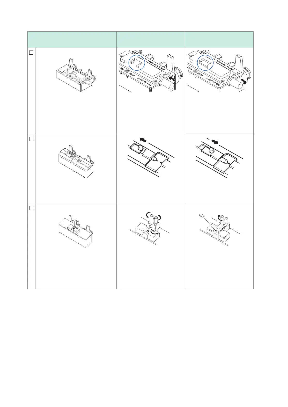
Test xture types
Open state during open
correction
Shorted state during short
correction
9263 SMD Test Fixture
*1
Measurable range: DC to 8 MHz
Maximum applied voltage: DC
40 V
Measurable sample dimensions: Test
sample width of 1 mm to 10 mm
This fixture is for measuring chip com-
ponents. (less than 10 m
Ω
residual re-
sistance after zero adjustment)
Turn the knob counterclockwise to
open the high and low electrodes
(use the width of the measure-
ment sample as the open spac-
ing).
Turn the knob clockwise to tighten
the high and low electrodes.
9677 SMD Test Fixture
*1
Measurable range: DC to 120 MHz
Maximum applied voltage: DC±40 V
Measurable sample dimensions: Test
sample width of 3.5±0.5 mm or less
Move the knob to open the high
and low electrodes (use the width
of the measurement sample as
the open spacing).
Move the knob to close the high
and low electrodes.
9699 SMD Test Fixture
*1
Measurable range: DC to 120 MHz
Maximum applied voltage: ±42 V peak
(AC+DC)
Measurable sample dimensions: Test
sample width of 1 mm to 4 mm
Test sample height of 1.5 mm or less
This xture is for the lower electrode.
Turn both knobs counterclock-
wise to loosen them (do not place
anything in the sample mounting
area).
Position the included short bar
in the sample mounting area
and turn the knobs clockwise to
secure the measurement sample
in place.
*1: Although the test xture appears to use a four-terminal setup, two terminals provide contact with the sample
since H
POT
and H
CUR
as well as L
POT
and L
CUR
are connected inside the xture and probe.