99
Verifying the Basic Trend
1
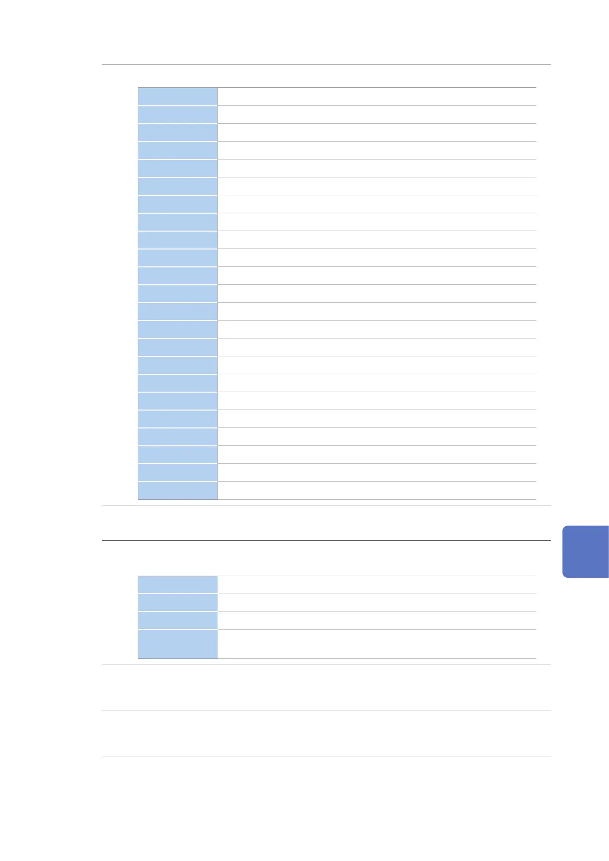
Enables you to set the display parameters.
Freq Frequency (200 ms)
Freq10s Frequency (10 sec)
Urms RMS voltage (200 ms)
Upk+ Voltage waveform peak (+)
Upk- Voltage waveform peak (-)
Udc Voltage DC value
Ucf Voltage crest factor
Uthd Voltage total harmonic distortion (calculation method THD-F / THD-R)
Uunb Voltage negative-phase unbalance factor
Uunb0 Voltage zero-phase unbalance factor
Irms RMS current (200 ms)
Ipk+ Current waveform peak (+)
Ipk- Current waveform peak (-)
Idc Current DC value
Icf Current crest factor
Ithd Current total harmonic distortion (calculation method THD-F / THD-R)
Iunb Current negative-phase unbalance factor
Iunb0 Current zero-phase unbalance factor
P Active power
S Apparent power
Q Reactive power
PF/DPF Power factor/displacement power factor
KF K factor
2
Enables you to set the display channel.
The channel which can be set differs according to the display items and wiring settings.
3
Set the type of graph to be displayed.
The type that can be set differs according to the display items.
MAX The maximum value during the recording interval is displayed.
AVG The average value during the recording interval is displayed.
MIN The minimum value during the recording interval is displayed.
ALL
The maximum, average, and minimum values during the recording interval
are displayed.
4
Set the zoom factor for the vertical axis of the graph.
Auto, ×1, ×2, ×5, ×10, ×25, ×50
5
Set the zoom factor for the horizontal axis (time axis) of the graph.
The horizontal axis (time axis) which can be set, differs according to the recording intervals.
8
Verifying the Trends (Fluctuations) in Measured Values (TREND Screen)

 Loading...


