61
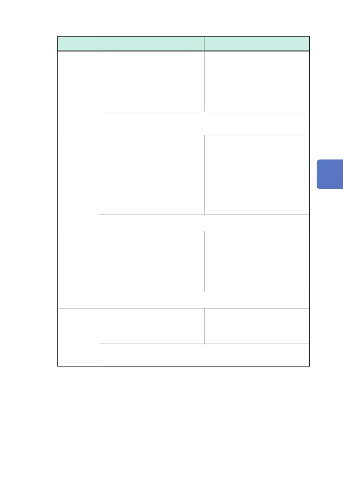
Checking Wiring
Wiring
judgment items
Judgment conditions Conrmation steps
Voltage input To determine the voltage value based on
the declared input voltage.
110% < CHECK
90% ≤ PASS ≤ 110%
80% ≤ CHECK < 90%
FAIL < 80%
• Has the declared input voltage been set
correctly?
• Are the voltage cords completely inserted
into the voltage input terminals?
• Are the tip clip and cord of the voltage
cord completely inserted?
• Is the tip clip of the voltage cord connected
to the metal parts of the measurement
line?
See “4.2 Wiring Method and Declared Input Voltage Settings” (p. 48).
See “4.3 Connecting Voltage Cords to Instrument” (p. 51).
See “4.6 Connecting Voltage Cords to Objects” (p. 55).
Current input FAIL will be displayed when input is less
than 1% of the current range. CHECK will
be displayed when input is less than 10% of
the current range.
Wiring cannot be checked when no current
is owing. Operate the equipment and
keep the current owing in order to check
the wiring. If the wiring cannot be checked
even if the equipment is operating, as exact
diagnosis cannot be done, visually check
for proper wiring before measuring.
• Are the current sensors properly inserted
into the current sensor input terminals?
• Are the current sensors correctly wired?
• Is the set current range too large for the
input level?
See “4.4 Connecting Current Sensors and Conguring Current Sensor Settings” (p. 52).
See “4.7 Attaching Current Sensors to Objects” (p. 56).
Voltage phase FAIL will be displayed when the voltage
phase exceeds the range (exceeds the
reference value ±10°).
• Are the wiring settings correct?
• Are the voltage cords correctly wired?
• The phases may have been incorrectly
laid out during wiring. Switch the voltage
cords and adjust the connections of the
current sensors so that PASS is displayed.
To recheck the phases, use a phase
detector to conrm that the phases are in
the correct sequence.
See “4.2 Wiring Method and Declared Input Voltage Settings” (p. 48).
See “4.6 Connecting Voltage Cords to Objects” (p. 55).
Current phase FAIL will be displayed when the current
phase sequence is incorrect.
• Are the current sensors connected in the
right places? (On both the wiring side, and
the input terminal of this instrument)
• Does the arrow of the current sensor point
to the load side?
See “4.2 Wiring Method and Declared Input Voltage Settings” (p. 48).
See “4.4 Connecting Current Sensors and Conguring Current Sensor Settings” (p. 52).
See “4.7 Attaching Current Sensors to Objects” (p. 56).
4
Wiring (WIRING Screen)

 Loading...


