90
Verifying the Harmonics Graph and Harmonics Numerical Values
5
Set the number of harmonic order to be displayed.
The Cursor moves to the selected order.
0 to 50
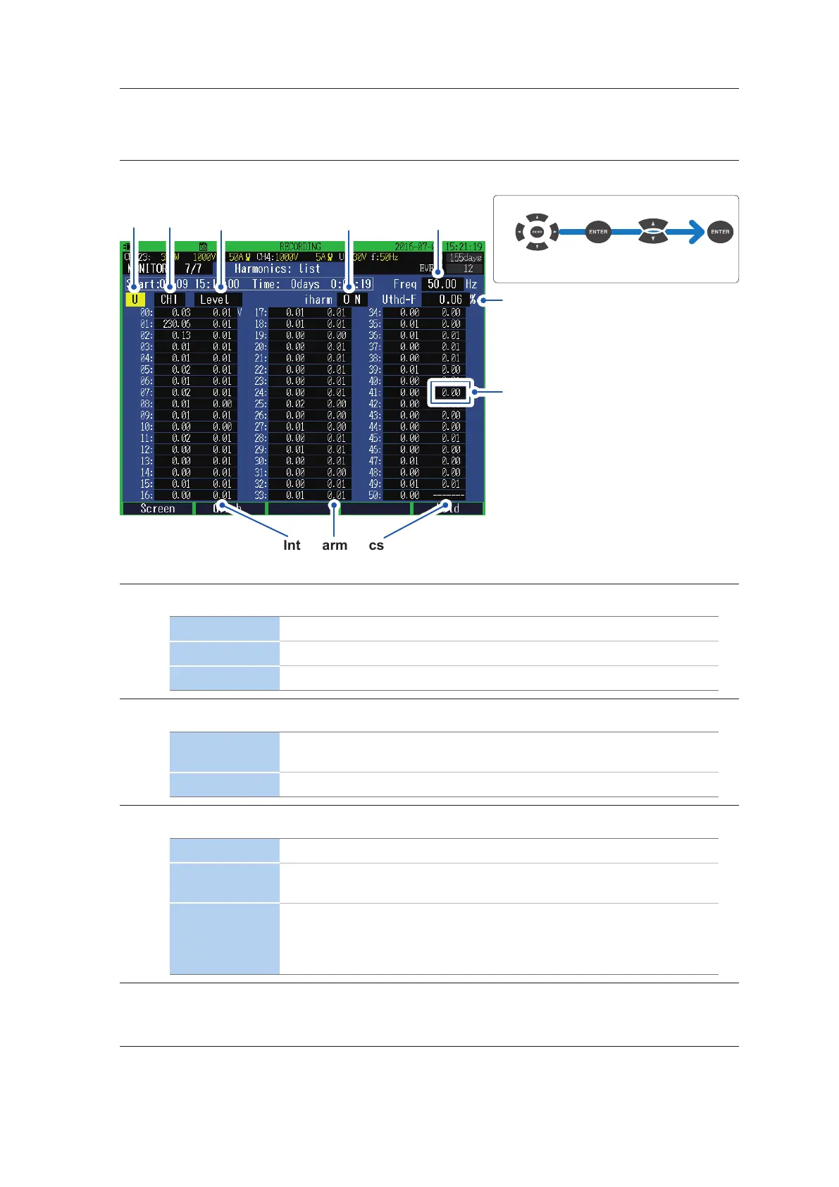
MONITOR, Harmonics: list screen
1
Measured value
of frequency
2 3
Total harmonic distortion
4
Move the cursor
Select
Example: 41.5th order
Interharmonics
*: See calculation method (p. 66).
1
Enables you to set the display parameters.
U Voltage
I Current
P Active power
2
Enables you to set the display channel.
CH1 to CH4
The voltage (U), current (I), and active power (P) of the selected channels
are displayed.
SUM Only the active power (P) is displayed.
3
Enables you to set the parameters to be displayed.
Level RMS voltage, RMS current, and active power
% of FND
Takes the fundamental wave component as 100% and shows a harmonic of
each order in terms of proportion to the fundamental wave component.
Phase
Voltage, current: The phase angle of each harmonic order when the phases
of the fundamental wave components of U1 are expressed in terms of 0°
Active power: The power factor of each harmonic order is expressed in
terms of angle
4
Enables you to set the display of the interharmonics.
ON, OFF

 Loading...


