96
Waveform Display Method
Displaying waveforms and measured values on the waveform and measured
value (WAVE+VALUE) screen. (This feature will be supported in rmware version
2.00.)
This screen displays waveforms and measured values. The timing between when on-screen
waveforms were recorded and when on-screen values were measured are not synchronized.
Starting waveform recording
Display screen [MEAS] > [WAVE] > [WAVE]
Waveform display area
Measured value display area
The measured values display area can
display 32 freely-selected basic measurement
parameters.
See “1.4 Basic Operation (Screen Display and
Layout)” (p. 20).
To stop display refresh of measured
values
Pressing the HOLD key can stop display
refresh of measured values. Waveform
recording is not stopped.
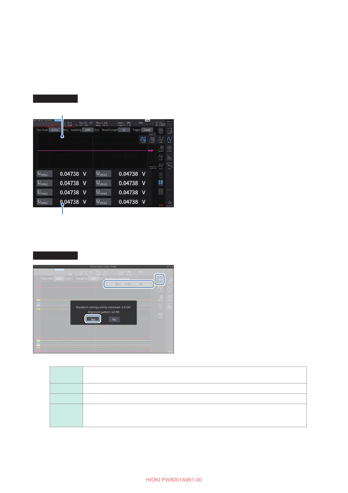
Aligning waveforms
There are four patters available to align waveforms.
Display screen [MEAS] > [WAVE]
22
33
11
1
Tap [Align].
2
Tap any one of the [ALIGN] patterns.
The conrmation dialog box is displayed.
3
Tap [Yes] to align the waveforms.
Wiring
Places waveforms of the same wiring conguration at the same position. The positions dier
according to the wiring conguration.
CH Places waveforms of the same channel at the same position.
U/I/Mt Places waveforms in the order of voltage, current, and motor from the top.
Default
Places waveforms separated into (1) voltage and current waveforms and (2) motor
waveforms. If the motor analysis option is not installed, voltage and current waveforms are
centrally located.
The vertical axis of the waveforms is positioned relative to the zero positions of each input.
• The vertical axis display magnication is adjusted to match the vertical axis size of the range and area.
• When waveforms are aligned, the colors of the waveforms are also changed. Colors dier depending on the
alignment pattern.

 Loading...


