141
Measured Value Save Data Format
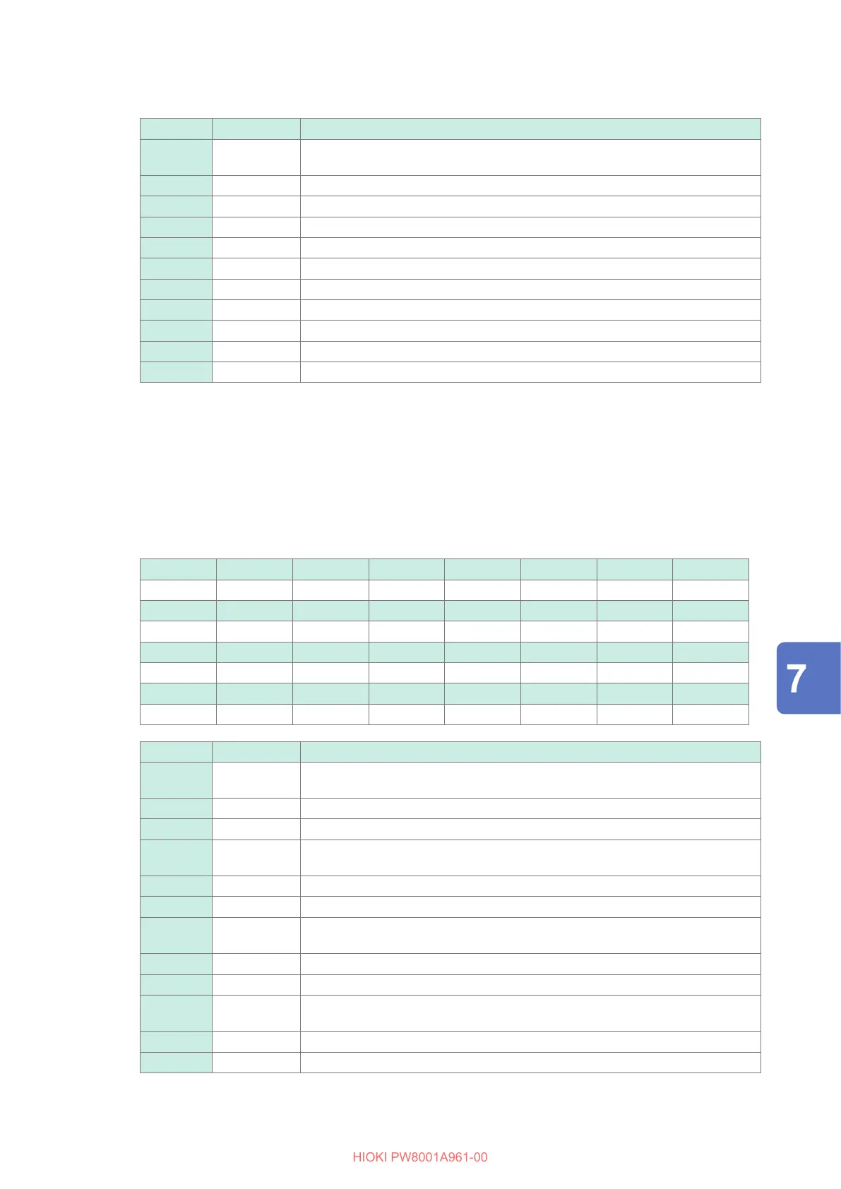
Bit Abbreviation Description
Bit 14 UCU Calculation was not possible. (for example, measurement data was invalid
because it was sampled immediately after range switching.)
Bit 13 ZP Power calculation (synchronization source) forced zero-crossing
Bit 12 ZI Current frequency forced zero-crossing
Bit 11 ZU Voltage frequency forced zero-crossing
Bit 10 DP No power calculation (synchronization source) data refreshing
Bit 9 DI No current frequency data refreshing
Bit 8 DU No voltage frequency data refreshing
Bit 3 RI Current overload
Bit 2 RU Voltage overload
Bit 1 PI Current peak-over
Bit 0 PU Voltage peak-over
Example: When Bit 12 (ZI, current frequency forced zero-crossing) and Bit 2 (RU, voltage overload)
are enabled, the status is represented as 1004 in hexadecimal notation.
For reference, the representation in binary would be 00000000000000000001000000000100.
Motor channel status (Status M)
Each of the 32 bits is assigned to contain the following information:
Bit 31 Bit 30 Bit 29 Bit 28 Bit 27 Bit 26 Bit 25 Bit 24
– – UCUG ZMG RMG UCUE ZME RME
Bit 23 Bit 22 Bit 21 Bit 20 Bit 19 Bit 18 Bit 17 Bit 16
– – UCUC ZMC RMC UCUA ZMA RMA
Bit 15 Bit 14 Bit 13 Bit 12 Bit 11 Bit 10 Bit 9 Bit 8
– – – – – – – –
Bit 7 Bit 6 Bit 5 Bit 4 Bit 3 Bit 2 Bit 1 Bit 0
– – – – – – – –
Bit Abbreviation Description
Bit 29 UCUG Ch. G calculation was not possible. (for example, measurement data was
invalid because it was sampled immediately after range switching.)
Bit 28 ZMG Ch. G motor synchronization source forced zero-crossing
Bit 27 RMG Overload while using Ch. G analog input
Bit 26 UCUE Ch. E calculation not possible (for example, measurement data was invalid
because it was sampled immediately after range switching.)
Bit 25 ZME Ch. E motor synchronization source forced zero-crossing
Bit 24 RME Overload while using Ch. E analog input
Bit 21 UCUC Ch. C calculation not possible (for example, measurement data was invalid
because it was sampled immediately after range switching.)
Bit 20 ZMC Ch. C motor synchronization source forced zero-crossing
Bit 19 RMC Overload while using Ch. C analog input
Bit 18 UCUA Ch. A calculation not possible (for example, measurement data was invalid
because it was sampled immediately after range switching.)
Bit 17 ZMA Ch. A motor synchronization source forced zero-crossing
Bit 16 RMA Overload while using Ch. A analog input
Saving Data and Managing Files

 Loading...


