144
Waveform/Analog Output (Waveform and D/A Output Option)
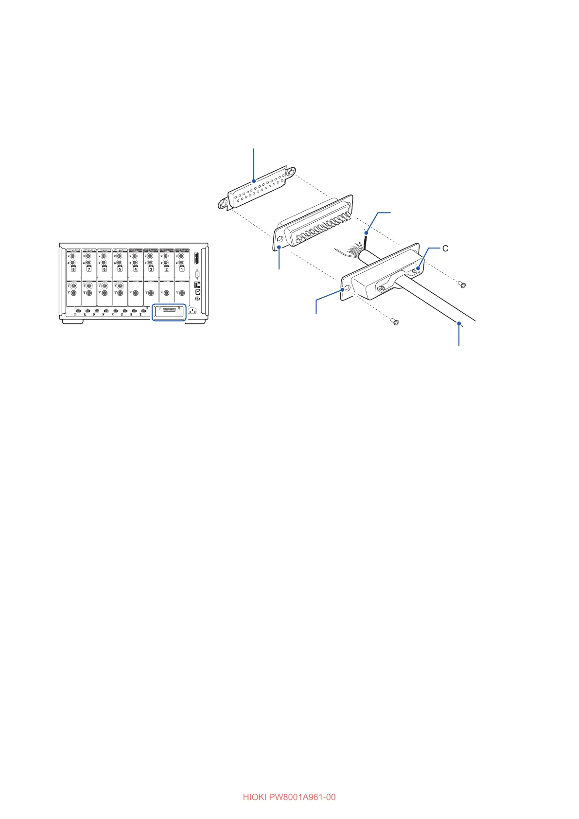
Connection method
Use the connector included with the instrument (DB-25PNR, DB19678-2R, Japan Aviation
Electronics Industry) or equivalent part to make connections using the external control terminal and
the output terminals.
Solder-type connector
WAVEFORM & D/A OUTPUT connector
Cord
Screw (M2.6
×
6)
Screw (M2.6
×
6)
Shielded cable
Cable bracket
Connector cover
Rear panel of instrument
• Solder wires in place securely.
• Be sure to secure the cable with the included screws (M2.6
×
6) along with the connector cover so
that the connector will not come loose.
• Grip the connector cover when connecting or disconnecting the connector.
• Be sure to use shielded cables for output and external control.
• If the cable’s shielding is not grounded, connect it to the connector cover or cable anchor shown
in the above gure.

 Loading...


