176
Connecting and Setting the RS-232C
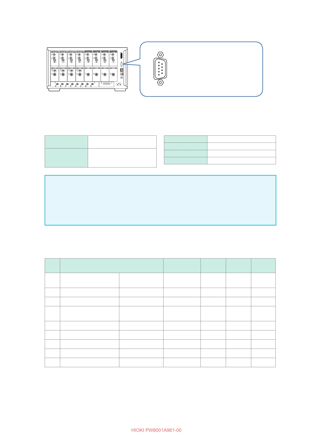
RS-232C connection
Recommended cable:
9637 RS-232C Cable
(1.8 m, 9 pins-9 pins, cross cable
9-pin D-sub plug)
Locking screws: #4-40
1
Connect the RS-232C cable to the instrument’s D-sub 9-pin connector and secure the cable
using the screws.
2
Set the controller communication protocol as follows (same settings as for the instrument).
Communications
method
Asynchronous
Communications
speed
9600 bps, 19200 bps, 38400 bps,
57600 bps, 115200 bps
(Follow the instrument setting.)
Stop bit 1 bit
Data length 8 bits
Parity check None
Flow control None
IMPORTANT
• When connecting the RS-232C cable to the controller (DTE), prepare a cross cable compatible
with the instrument’s connector and controller’s connector.
• When using a USB-serial cable, a gender changer, and a straight-cross converter may be
required. Prepare them according to the specications of the instrument’s connector and USB-
serial cable connector.
The input and output connectors use the terminal (DTE) specications.
Pin Nos. 2, 3, 5, 7, and 8 are used for this instrument. Other pins are not to be used.
Pin
No.
Interchange circuit name
CCIT circuit
No.
EIA code JIS code
Common
code
1 Data channel receiving
carrier detection
Carrier Detect 109 CF CD DCD
2 Received data Receive Data 104 BB RD RxD
3 Sent data Send Data 103 BA SD TxD
4 Data terminal ready Data Terminal
Ready
108/2 CD ER DTR
5 Signal ground Signal Ground 102 AB SG GND
6 Data set ready DATA Set Ready 107 CC DR DSR
7 Request to send Request to Send 105 CA RS RTS
8 Clear to send Clear to Send 106 CB CS CTS
9 Ring indicator Ring Indicator 125 CE CI RI

 Loading...


