204
Detailed Specications of Measurement Parameters
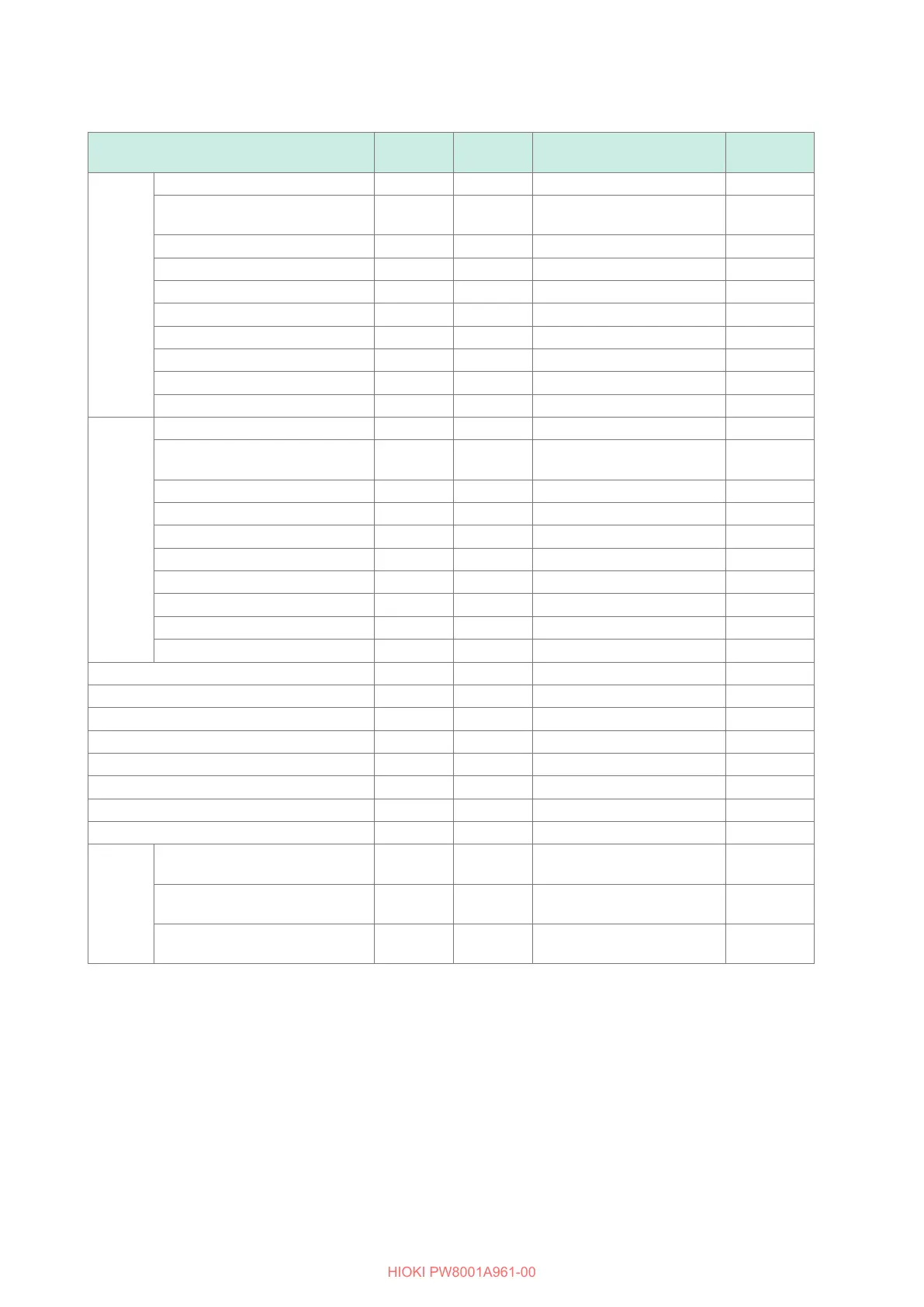
Measurement item Notation Unit Display range
Polarity
(+/−)
Voltage
RMS value Urms V 0% to 150%*
1
of the U range
RMS equivalent of average
rectied value
Umn V 0% to 150%*
1
of the U range
AC component Uac V 0% to 150%*
1
of the U range
Simple average Udc V 0% to 150%*
2
of the U range
Fundamental wave component Ufnd V 0% to 150%*
1
of the U range
Waveform peak + Upk+ V 0% to 300%*
2
of the U range
Waveform peak − Upk− V 0% to 300%*
2
of the U range
Total harmonic distortion Uthd % 0.000 to 500.000
Ripple factor Urf % 0.000 to 500.000
Unbalance rate Uunb % 0.000 to 100.000
Current
RMS value Irms A 0% to 150% of the I range
RMS equivalent of average
rectied value
Imn A 0% to 150% of the I range
AC component Iac A 0% to 150% of the I range
Simple average Idc A 0% to 150% of the I range
Fundamental wave component Ifnd A 0% to 150% of the I range
Waveform peak + Ipk+ A 0% to 300%*
3
of the I range
Waveform peak − Ipk− A 0% to 300%*
3
of the I range
Total harmonic distortion Ithd % 0.000 to 500.000
Ripple factor Irf % 0.000 to 500.000
Unbalance rate Iunb % 0.000 to 100.000
Active power P W 0% to 150% of the P range
Fundamental wave active power Pfnd W 0% to 150% of the P range
Apparent power S VA 0% to 150% of the P range
Fundamental wave apparent power Sfnd VA 0% to 150% of the P range
Reactive power Q Var 0% to 150% of the P range
Fundamental wave reactive power Qfnd Var 0% to 150% of the P range
Power factor
λ
— 0.00000 to 1.00000
Fundamental wave power factor
λ
fnd — 0.00000 to 1.00000
Phase
angle
Voltage phase angle
θ
U degree 0.000 to 180.000
0.000 to 360.000*
4
—
Current phase angle
θ
I degree 0.000 to 180.000
0.000 to 360.000*
4
—
Power phase angle
φ
degree 0.000 to 180.000
0.000 to 360.000*
4
—
*1: Only for the 1500 V range, 135%.
This range does not change even when the delta conversion function is used.
*2: Only for the 1500 V range, 135%.
*3: Only for the 5 V range of Probe 2, 150%.
*4: Selectable
When the Upk+ or Upk− voltage waveform peak, or the Ipk+ or Ipk− current waveform peak exceeds the display
range, a peak-over condition is considered to have occurred.

 Loading...


