18
Part Names and Functions
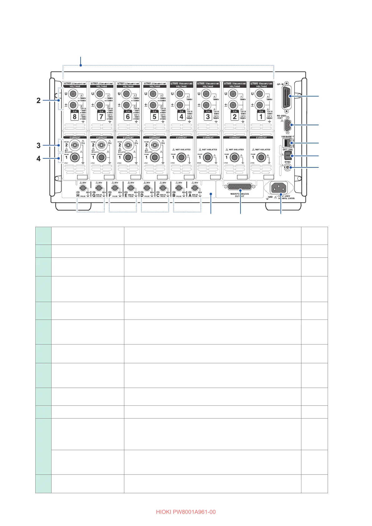
Rear
10101111
55
66
77
88
99
1212
11
Motor 4 Motor 3 Motor 2 Motor 1
33
44
22
11
Input channels
Insert up to 8 channels in the form of modules that accept input of
voltage and current for one phase of power.
—
22
Voltage input terminals Connect Hioki’s optional voltage cords. p. 34
33
Probe 2 terminals
(For current sensors)
Connect sensors of the voltage output type, including a current probe
and CT.
p. 37
44
Probe 1 terminals
(For high performance
current sensors)
Connect Hioki’s optional current sensors. The instrument
automatically recognizes current sensors. It also supplies power to
the current sensors.
p. 35
55
GP-IB connector
Controls the instrument remotely using GP-IB.
Transfers measured data to a computer.
p. 173
66
RS-232C connector
(D-sub 9 pins)
Controls the instrument remotely from a computer or controller via
serial RS-232C communications.
Controls starting and stopping of integration with a contact switch.
p. 175
77
RJ-45 connector
(Gigabit Ethernet)
Controls the instrument remotely over a LAN.
Transfers measured data to a PC.
p. 158
88
Optical link connector
(This feature will be supported in rmware version 2.00.)
Connect L6000 Optical Cable.
Performs advanced measurement using 2 synchronized instruments.
—
99
BNC synchronization
connector
(This feature will be supported in rmware version 2.00.)
Performs measurement using up to 4 synchronized instruments.
—
1010
Power supply inlet Connect the included power cord. p. 39
1111
Waveform and D/A
output option
You can input the instrument’s output into a recorder to record data
over an extended period of time.
You can also input this signal to an oscilloscope to observe the
waveform.
p. 143
CAN/CAN FD interface
option
(This feature will be supported in rmware version 2.00.)
Measured data can be output as CAN/CAN FD signals to the CAN
bus in real time.
—
1212
Motor analysis option
(External input)
You can input torque sensor and tachometer output to measure
motor output.
p. 78

 Loading...


