244
Rackmount Fittings
Installation instructions
WARNING
Use M4
×
16 mm screws to attach the ttings to the PW8001 main body.
If ttings are attached with other screws, the instrument may be damaged, causing a
risk of bodily injury.
IMPORTANT
• Reinforce the inside of the rack with commercially available support braces or other parts as
appropriate to bear the weight of the instrument.
• Leave at least 30 mm of space on every surface other than the underside to keep the
instrument’s temperature from rising.
Leave at least 15 mm of space underneath the instrument (the height of its feet).
Tools to be prepared:
Rackmount tting (JIS-compliant Z5301, EIA-compliant Z5300), hexagon wrench (width across ats: 2.5 mm),
Phillips screwdriver (No. 2)
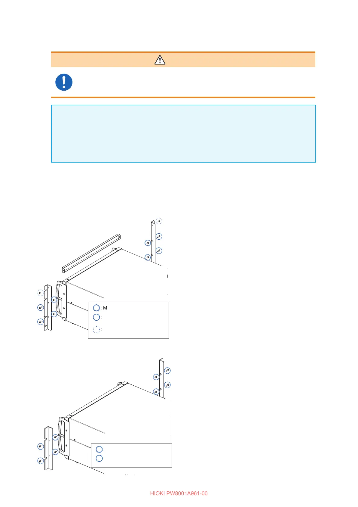
To mounting the instrument in a JIS-compliant rack
: M4
×
16 mm binding head
machine screw
: M4
×
8 mm cap bolt
: M3
×
8 mm binding head
machine screw
44
44
33
33
22
22
1
Turn o the instrument and remove all
cables.
2
Remove the M4 cap bolts (two each on the
left and right) that hold each handle in place
using the hexagon wrench.
Keep the removed M4 cap bolts.
3
Attach the rackmount ttings to the
instrument with M4
×
16 mm screws (two
each on the left and right).
4
Attach the rackmount tting (blank panel)
with M3
×
8 mm screws (one each on the left
and right).
To mounting the instrument in a EIA-compliant rack
: M4
×
16 mm binding head
machine screw
: M4
×
8 mm cap bolt
22
22
33
33
1
Turn o the instrument and remove all
cables.
2
Remove the M4 cap bolts (two each on the
left and right) that hold each handle in place
using the hexagon wrench.
Keep the removed M4 cap bolts.
3
Attach the rackmount ttings to the
instrument with M4
×
16 mm screws (two
each on the left and right).

 Loading...


