79
Motor Measurement (Motor Analysis-Equipped Model)
To connect torque meters and tachometers
Necessary items: L9217 Connection Cord (necessary quantity),
device to be connected (such as torque sensor and tachometer)
1
Verify that the instrument and the device being connected have been turned o.
2
Connect the device’s output terminal to the instrument with a connection cord.
See “Connection examples of motor analysis” (p. 81).
3
Turn on the instrument.
4
Turn on the connected device.
Connection method
There are several dierent operating modes and connection patterns available for the motor inputs.
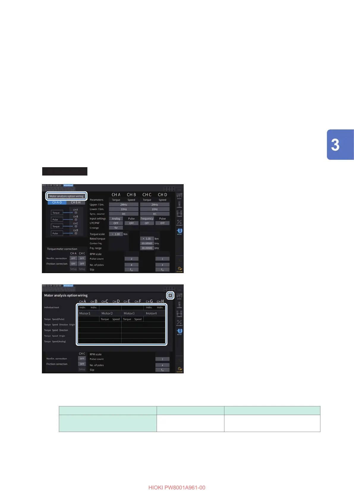
Display screen [INPUT] > [MOTOR]
11
1
Tap [Motor analysis option wiring] to
open the settings window.
2
Select the operation mode for the
motor analysis option channels.
3
Tap [
×
] to close the setting window.
22
33
[Individual input] mode
The motor inputs can be used as independent analog DC inputs or as pulse inputs.
Operating mode Settable channels Description
Individual Input AB, CD, EF, GH For measuring voltage signals and
pulse signals
Using this mode can measure and display the signal from a voltage-output sensor, or measure the frequency
of a pulse input and display the waveform.
Displaying Power Numerically

 Loading...


