Table 4-41 Connecting cables to the smoke sensor
Core Wires of the Network Cable Cables for the Smoke Sensor
Core wire 1 (orange-white), core wire
8 (brown)
GND (black)
Core wire 3 (green-white) +12 V (red)
Core wire 6 (green) Normally closed end (yellow)
Core wire 7 (brown-white) Common end (green)
None (reserved, cable connection not
required, only insulation required)
Normally opened end (blue)
Step 4 Connect one end of the RJ45 network cable to the AI/DI port on the ECC800-Pro
collector or a UIM20A expansion module.
----End
4.3.6.5 Connecting a Monitoring Cable to a Temperature and Humidity
Sensor
Procedure
Step 1 Connect one end of the network cable to the pins of the temperature and
humidity sensor.
● Connect the T/H sensor (BOM number: 33010346) to the RS485 port.
● Connect the T/H sensor (BOM number: 02312PBL) to the RJ45 port.
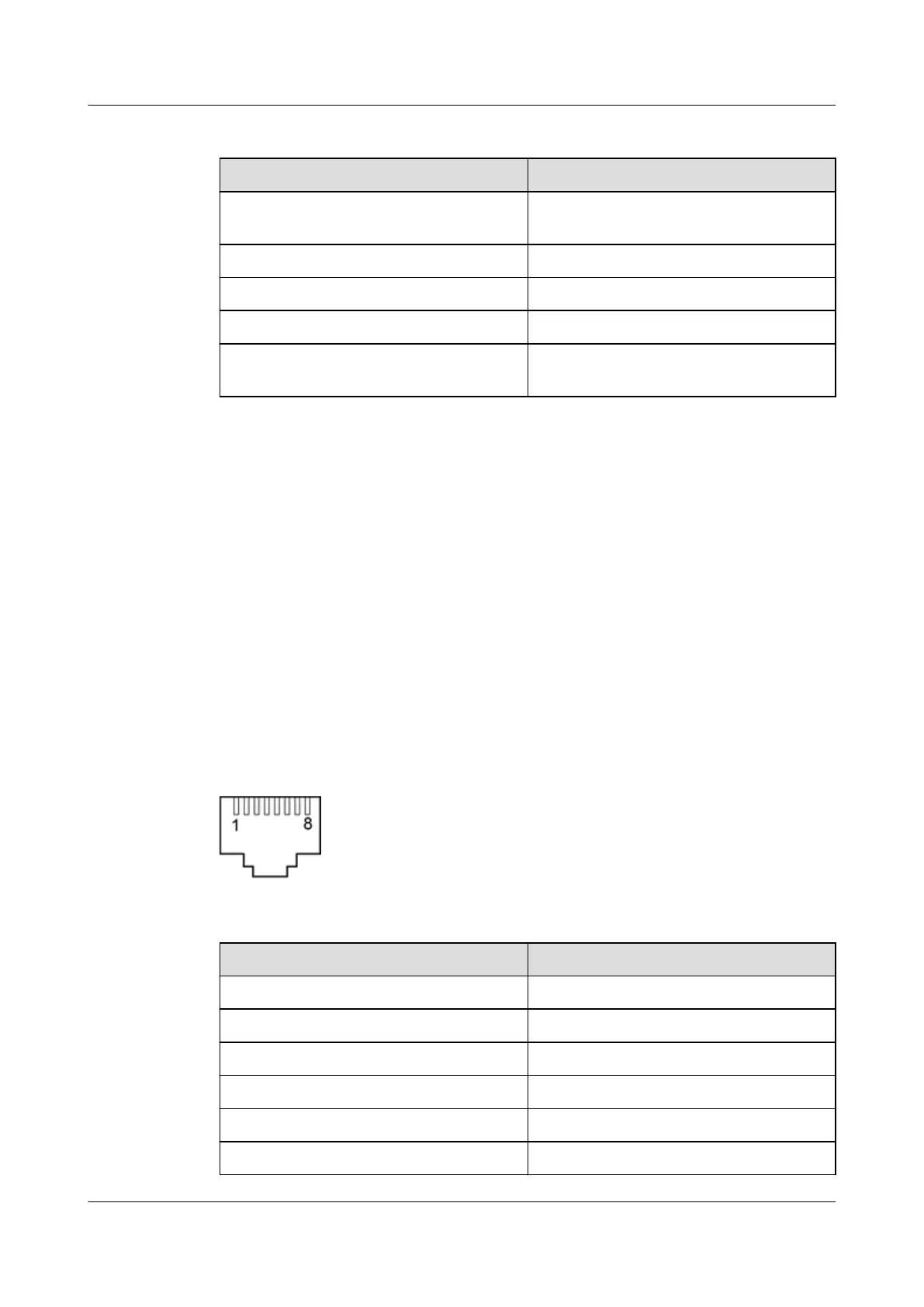
Figure 4-37 Interface for the T/H sensor network cable
Table 4-42 Network cable wire sequence
PIN
Denition
pin1 RS485 (A)
pin2 RS485 (B)
pin3 V+12V input
pin4 -
pin5 -
pin6 -
iMaster NetEco
Device Installation and Commissioning Guide (Data
Center) 4 Connecting Monitoring Cables to Devices
Issue 02 (2021-05-12) Copyright © Huawei Technologies Co., Ltd. 118
 Loading...