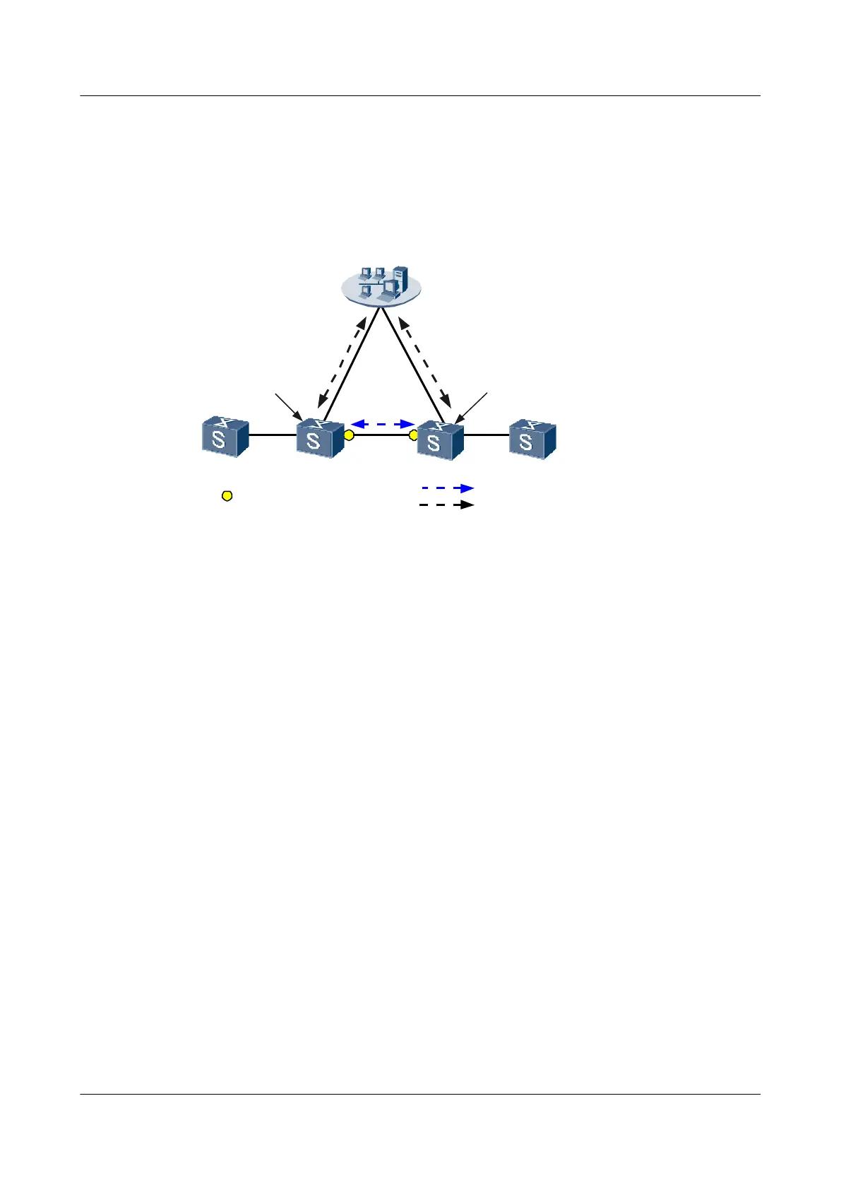
Switch A and Switch B need to obtain the status of each other through the LLDP protocol and
the NMS should locate Switch A and Switch B based on the management addresses to discover
the network topology. When a management address changes, LLDP is disabled globally, or
neighbor information changes, Switch A and Switch B should send LLDP traps to the NMS.
Figure 4-2 Networking diagram for configuring LLDP
SwitchA SwitchB
NMS
SNMP
SNMP
LLDPDU
SNMP packet
10.10.10.210.10.10.1
LLDPDU packet
NMS: Network Management System
LLDP interface
Configuration Roadmap
The configuration roadmap is as follows:
1. Enable the LLDP trap function on Switch A and Switch B.
2. Enable LLDP globally on Switch A and Switch B.
3. Configure the management addresses of Switch A and Switch B.
4. Configure the LLDP attributes of Switch A and Switch B.
Data Preparation
To complete the configuration, you need the following data:
l The management address of Switch A is 10.10.10.1, and the management address of Switch
B is 10.10.10.2.
l The interval for sending LLDP packets is 60 seconds. The delay for sending LLDP packets
is 9 seconds. The delay for sending traps when neighbor information changes is 10 seconds.
Procedure
Step 1 Enable the LLDP trap function on Switch A and Switch B.
# Configure Switch A.
<Quidway> system-view
[Quidway] sysname SwitchA
[SwitchA] snmp-agent trap enable feature-name lldptrap
Quidway S9300 Terabit Routing Switch
Configuration Guide - Network Management 4 LLDP Configuration
Issue 03 (2010-09-20) Huawei Proprietary and Confidential
Copyright © Huawei Technologies Co., Ltd.
4-17

 Loading...


