port hybrid untagged vlan 100
#
ntp-service unicast-peer 3.0.1.32
#
return
3.6.3 Example for Configuring NTP Authentication in Broadcast
Mode
Networking Requirements
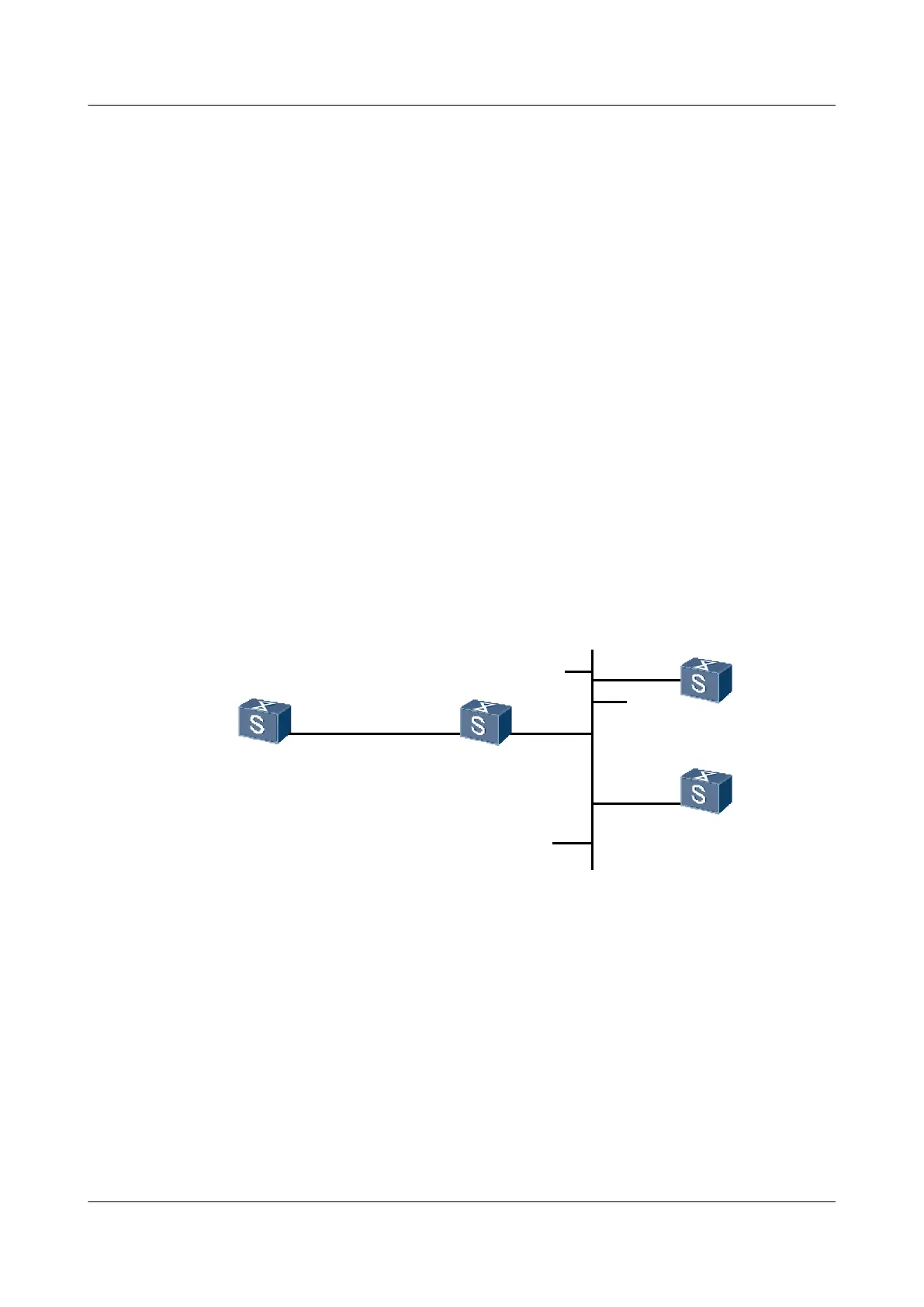
As shown in Figure 3-4,
l Switch C and Switch D are on the same network segment; Switch A is on another network
segment; Switch F connects the two network segments.
l As the NTP broadcast server, Switch C uses the local clock as the NTP master clock, which
is a stratum-3 clock. Switch C sends broadcast packets through VLANIF10, namely,
GE1/0/0.
l Switch D uses VLANIF10, namely, GE1/0/0, to listen to the broadcast packets.
l Switch A uses VLANIF20, namely, GE1/0/0, to listen to the broadcast packets.
l NTP authentication needs to be enabled.
Figure 3-4 Networking diagram for configuring the NTP broadcast mode
GE1/0/0
VLANIF20
1.0.1.11/24
SwitchA SwitchF
SwitchC
SwitchD
1.0.1.2/24
GE2/0/0
VLANIF10
3.0.1.2/24
GE1/0/0
VLANIF10
3.0.1.31/24
GE1/0/0
VLANIF10
3.0.1.32/24
GE1/0/0
VLANIF20
Configuration Roadmap
The configuration roadmap is as follows:
1. Configure Switch C as the NTP broadcast server.
2. Configure Switch A and Switch D as the NTP broadcast clients.
3. Configure NTP authentication on Switch A, Switch C, and Switch D.
Data Preparation
To complete the configuration, you need the following data:
Quidway S9300 Terabit Routing Switch
Configuration Guide - Network Management 3 NTP Configuration
Issue 03 (2010-09-20) Huawei Proprietary and Confidential
Copyright © Huawei Technologies Co., Ltd.
3-29

 Loading...


