6.37.22 Example for Configuring the PWE3 Ping Test on a Single-
Hop PW
Networking Requirements
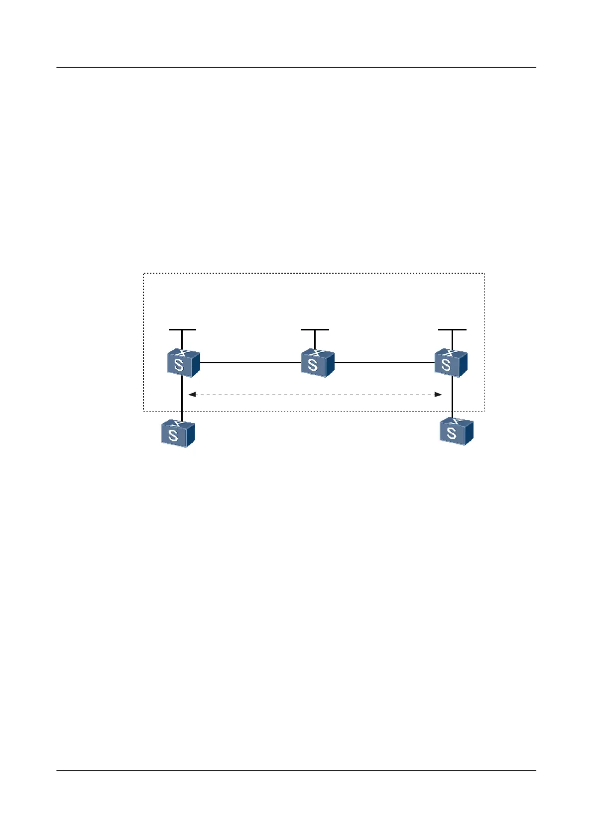
As shown in Figure 6-24, CE-A and CE-B are connected to PE-A and PE-B respectively. PE-
A and PE-B are connected through the MPLS backbone network. A dynamic PW needs to be
set up between PE-A and PE-B through the LSP tunnel.
The PWE3 Ping function of the single-hop PW needs to be performed to test the connectivity
of the PW between PE-A and PE-B.
Figure 6-24 Networking diagram for configuring the PWE3 Ping test on the single-hop PW
PE-B
CE-A
CE-B
Loopback0
192.2.2.2/32
GE2/0/0
VLANIF130
10.2.2.1/24
GE2/0/0
VLANIF130
10.2.2.2/24
GE1/0/0
VLANIF120
10.1.1.2/24
GE2/0/0
VLANIF120
10.1.1.1/24
GE1/0/0
VLANIF110
100.1.1.1/24
GE1/0/0
VLANIF110
GE1/0/0
VLANIF140
GE1/0/0
VLANIF140
100.1.1.2/24
PW
Loopback0
192.4.4.4/32
Loopback0
192.3.3.3/32
PE-A
P
MPLS Backbone
Configuration Roadmap
The configuration roadmap is as follows:
1. Run the IGP protocol on the backbone network to make the routes between Switches on
the backbone network reachable.
2. Configure the basic MPLS functions on the backbone network and set up an LSP tunnel.
Set up the MPLS LDP peer relation between the two PE devices on the two ends of the
PW.
3. Create an MPLS L2VC connection between the two PE devices.
4. Configure a PWE3 Ping test on the single-hop PW on PE-A.
Data Preparation
To complete the configuration, you need the following data:
l L2VC IDs of the two ends of the PW, which must be the same
l MPLS LSR-IDs of the PE and P devices
Quidway S9300 Terabit Routing Switch
Configuration Guide - Network Management 6 NQA Configuration
Issue 03 (2010-09-20) Huawei Proprietary and Confidential
Copyright © Huawei Technologies Co., Ltd.
6-205

 Loading...


