l Switch A uses VLANIF 20, namely, GE1/0/0, to listen to the multicast packets.
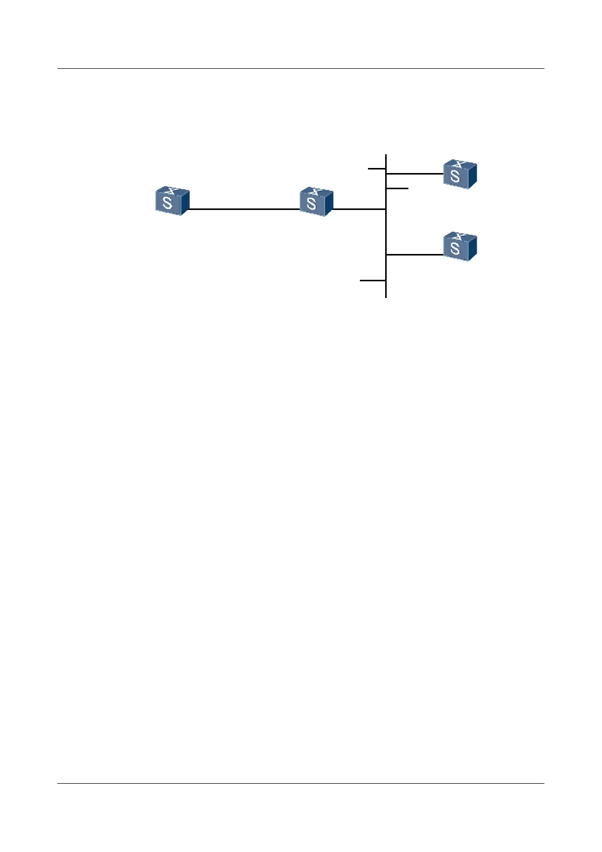
Figure 3-5 Networking diagram for configuring the NTP multicast mode
GE1/0/0
VLANIF20
1.0.1.11/24
SwitchA SwitchF
SwitchC
SwitchD
1.0.1.2/24
GE2/0/0
VLANIF10
3.0.1.2/24
GE1/0/0
VLANIF10
3.0.1.31/24
GE1/0/0
VLANIF10
3.0.1.32/24
GE1/0/0
VLANIF20
Configuration Roadmap
The configuration roadmap is as follows:
1. Configure Switch C as the NTP multicast server.
2. Configure Switch A and Switch D as the NTP multicast clients.
Data Preparation
To complete the configuration, you need the following data:
l IP address of each interface
l Stratum count of the NTP master clock
Procedure
Step 1 Configure the IP addresses of the Switches and ensure that the routes between them are
reachable.The configuration procedure is not mentioned.
Step 2 Configure the IP addresses of the Switches.
Configure the IP address of each interface according to Figure 3-5.
# Configure the IP address of the VLANIF interface on Switch C.
<SwitchC> system-view
[SwitchC] vlan 10
[SwitchC-Vlan10] quit
[SwitchC] interface gigabitethernet 1/0/0
[SwitchC-GigabitEthernet1/0/0] port hybrid pvid vlan 10
[SwitchC-GigabitEthernet1/0/0] port hybrid untagged vlan 10
[SwitchC-GigabitEthernet1/0/0] quit
[SwitchC] interface vlanif 10
[SwitchC-Vlanif10]ip address 3.0.1.31 24
[SwitchC-Vlanif10]quit
# Configure the IP address of the VLANIF interface on Switch D.
3 NTP Configuration
Quidway S9300 Terabit Routing Switch
Configuration Guide - Network Management
3-34 Huawei Proprietary and Confidential
Copyright © Huawei Technologies Co., Ltd.
Issue 03 (2010-09-20)

 Loading...


