4.5.2 Example for Configuring LLDP When an Eth-Trunk Is Used
on a Network
Networking Requirements
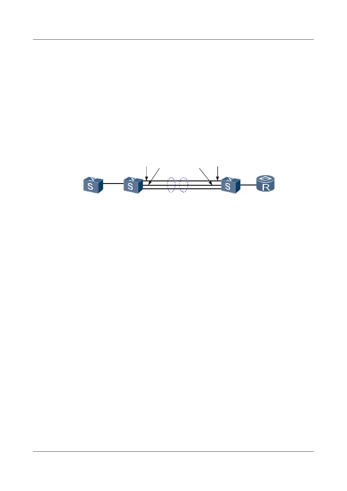
As shown in Figure 4-3, Switch A and Switch B are connected through the Eth-Trunk. On each
switch, three interfaces are added to the Eth-Trunk. In addition, two Eth-Trunk interfaces on
each switch should be able to send and receive LLDP packets, and thus the two switchs can
obtain status information about each other. The other Eth-Trunk interface on each switch is
disabled from sending or receiving LLDP packets.
Figure 4-3 Networking diagram for configuring LLDP when an Eth-Trunk is used on the
network
SwitchA
GE1/0/1
GE1/0/2
GE1/0/3
GE2/0/3
GE2/0/2
GE2/0/1
Eth-Trunk1
10.10.10.1
10.10.10.2
SwitchB
Configuration Roadmap
The configuration roadmap is as follows:
1. Enable LLDP globally on Switch A and Switch B.
2. Configure the management addresses of Switch A and Switch B so that the NMS can
identify the switchs.
3. Add the Ethernet interfaces of Switch A and Switch B to the Eth-Trunk.
4. Disable LLDP on the Eth-Trunk member interfaces of Switch A and Switch B.
Data Preparation
To complete the configuration, you need the following data:
l Management address of Switch A (10.10.10.1), and the management address of Switch B
(10.10.10.2)
l Number of the Eth-Trunk that connects Switch A and Switch B, and the number of the
interfaces that are added to the Eth-Trunk
Procedure
Step 1 Enable LLDP globally on Switch A and Switch B.
# Configure Switch A.
<Quidway> system-view
[Quidway] sysname SwitchA
[SwitchA] lldp enable
# Configure Switch B.
4 LLDP Configuration
Quidway S9300 Terabit Routing Switch
Configuration Guide - Network Management
4-22 Huawei Proprietary and Confidential
Copyright © Huawei Technologies Co., Ltd.
Issue 03 (2010-09-20)

 Loading...


