17-19 Operators’ Manual
990400 Rev C 2010 May 1
10-14
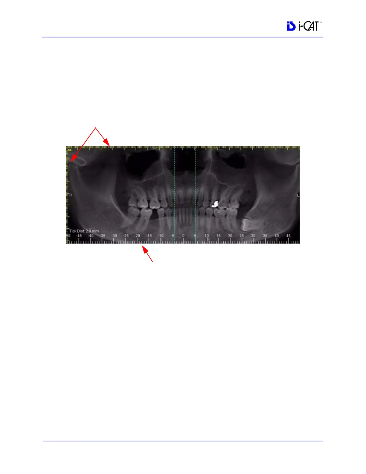
NOTE: When adding a Panoramic image to a report from the
Implant Planning screen, (Panoramic selected for Single
Images), be aware that a slice location indicator scale is
displayed at the bottom of the image. Each tick on this scale
represents the location of a slice. It is NOT a measuring tool. The
yellow vertical and horizontal scales (mm) should be used for
measuring.
Image Size
• Life Size – used to depict the image in life size (able to
measure directly on the paper). The drop-down list box
allows specifying where the image originated. For example,
if Left Top Corner is selected, the image fills in the image
box starting in the top left corner.
• Fit to Window – used to autofit the image to the available
page area.
Image Attributes
• Overlays – when selected, markings that were generated on
the image within Vision are displayed
• Window and Level – adjusts the brightness and contrast
• Ruler – designates where the ruler appears on the image
The Image Properties box can be displayed at any time by right-
clicking inside the image box and selecting Properties.
Vertical and Horizontal Scales (Measuring Tools)
Slice Location Indicator (Do Not Use as a Measuring Tool)