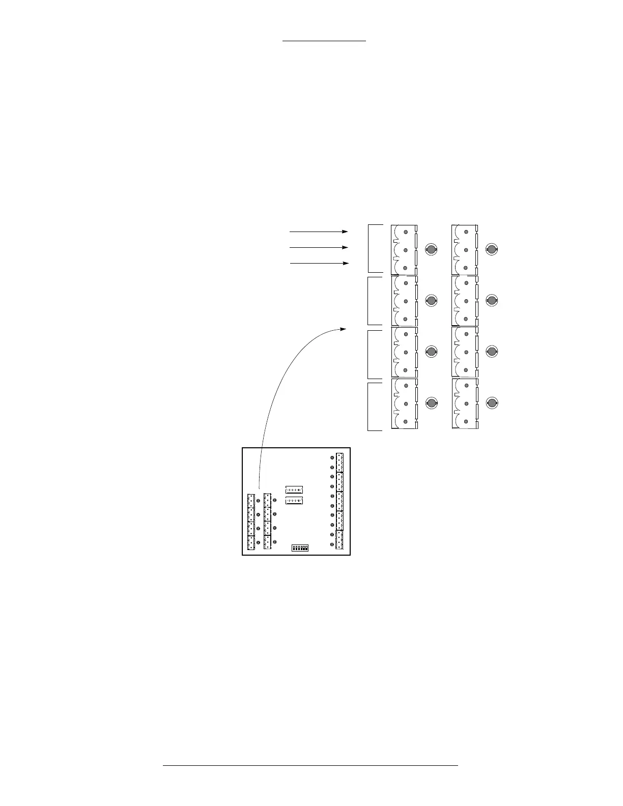
Figure 3-35: Configuration of Outputs
S300 Expansion Enclosures CK721-A Installation and Operation
3-52 24-10349-8 Rev. B
This document contains confidential and proprietary information of Johnson Controls, Inc.
© 2012 Johnson Controls, Inc.
Output Relay Wiring
Relay outputs are provided for connecting to customer-supplied devices. Each
output relay can provide general purpose low or intermediate power control to the
device. The relay will switch 2A at 30 VDC.
All outputs supply a normally open, common,
and normally closed relay contact.
The state of each relay is indicated by a red LED adjacent to each set of relay contact
outputs. The LED is lit when the relay is energized.
NO
C
NC
NO
C
NC
NO
C
NC
NO
C
NC
OUTPUT 4
OUTPUT 3 OUTPUT 2
OUTPUT 1
Normally Open
Common
Normally Closed
S300 IO8 S300 SIO8
J1D
J1C
J1B
J1A
J2D
J2C
J2B
J2A