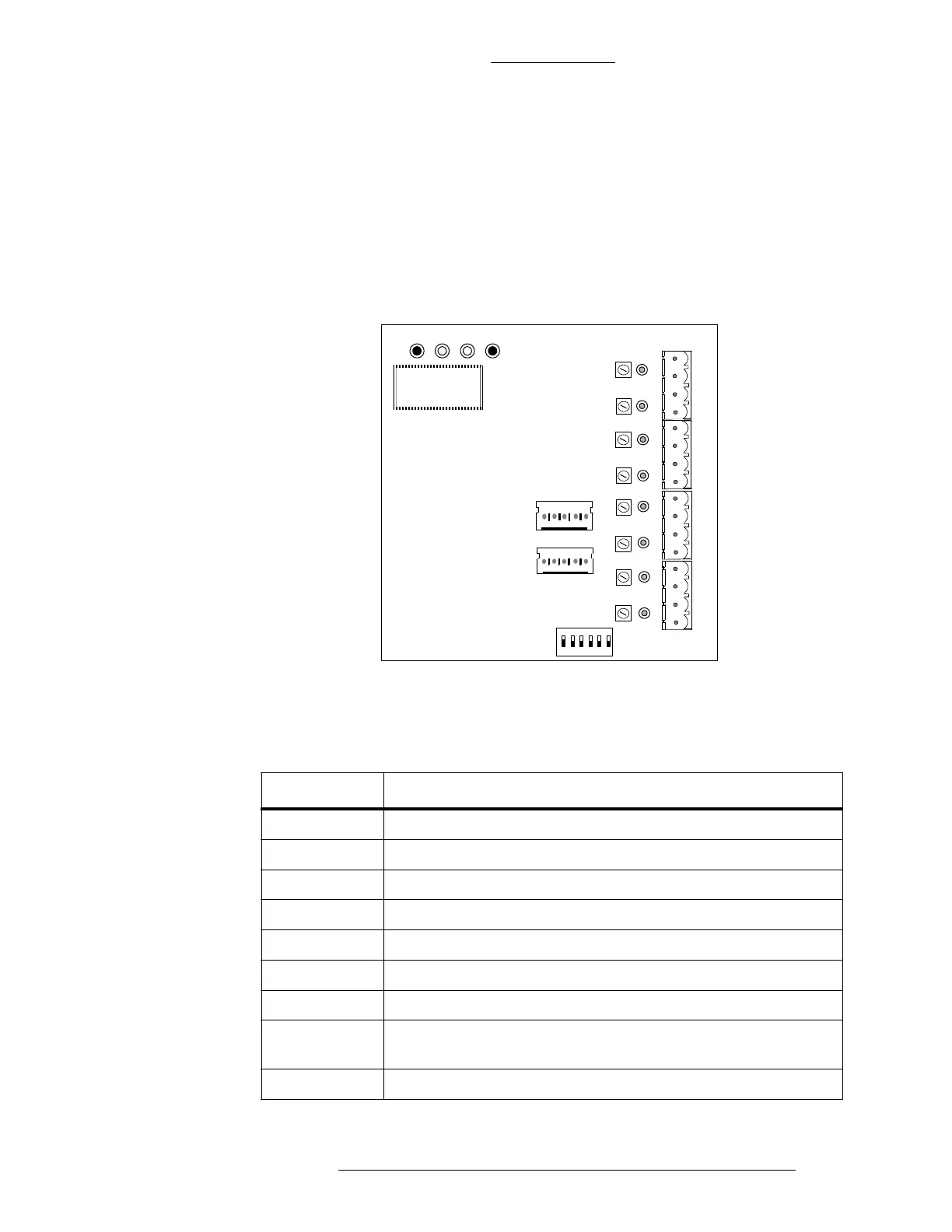
Figure 3-30: S300-SI8 Module
Table 3-22: S300-SI8 Components
Connectors Description
J3 RS-485 Input
J4 RS-485 Output
J6A Alarm Inputs 1 and 2
J6B Alarm Inputs 3 and 4
J6C Alarm Inputs 5 and 6
J6D Alarm Inputs 7 and 8
SW1 Address Settings
System LEDs Indicates when data is transmitted or received and the presence
of 5 an
d 12 VDC, as shown in Figure 3-30.
U1 S300-SI8 Firmware
CK721-A Installation and Operation S300 Expansion Enclosures
24-10349-8 Rev. B 3-47
This document contains confidential and proprietary information of Johnson Controls, Inc.
© 2012 Johnson Controls, Inc.
S300-SI8 Supervised Alarm Input Module
The S300-SI8 module provides:
Eight four-state (open or short circuit, alarm, and secure) alarm inputs.
A three-color LED input indicator for each alarm showing:
Off - Open Green - Secure
Yellow - Short Red - Alarm
J3
J4
RX TX
5V
12V
U1
J6D
J6C
J6B
J6A
SW1
16