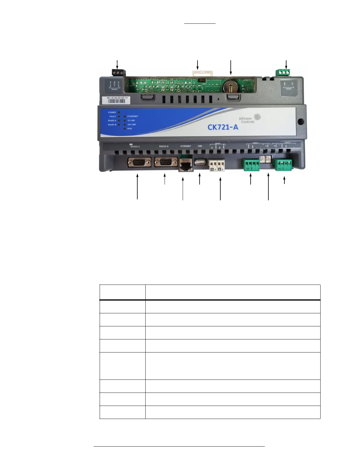
RS232 A
connector
IN1 and IN2
binary inputs
RS485B
connector
Binary output Lithium battery 24VDC power
Ethernet
connector
RJ45
DIN clip
RS485A
connector
USB connector
(not used)
RS232 B
connector
End-of-Line
switches
CK721-A and S300-DIN Enclosures CK721-A Installation and Operation
2-2 24-10349-8 Rev. B
This document contains confidential and proprietary information of Johnson Controls, Inc.
© 2012 Johnson Controls, Inc.
LEDs on the CK721-A
There are nine LEDs on the CK721-A board. Their functions are shown in
Table 2-1.
Table 2-1: CK721-A LED Functions
LED Function
POWER ON steady when power is applied.
FAULT OFF to indicate normal operation.ON indicates a general fault.
RS485 A Flashes/flickers to indicate data transmit.
RS485 B Flashes/flickers to indicate data transmit.
ETHERNET Flashes/flickers to indicate da
ta traffic on the Ethernet
connection. OFF indicates no Ethernet data traffic, and probably
indicates a dead Ethernet network or bad Ethernet connection.
10/LINK ON to indicate 10 Mbit connection is established.
100/LINK ON to indicate 100 Mbit connection is established.
RUN This LED is currently not used (always OFF).