Figure 2-11: CK721-A Module Mounted on a DIN Rail.
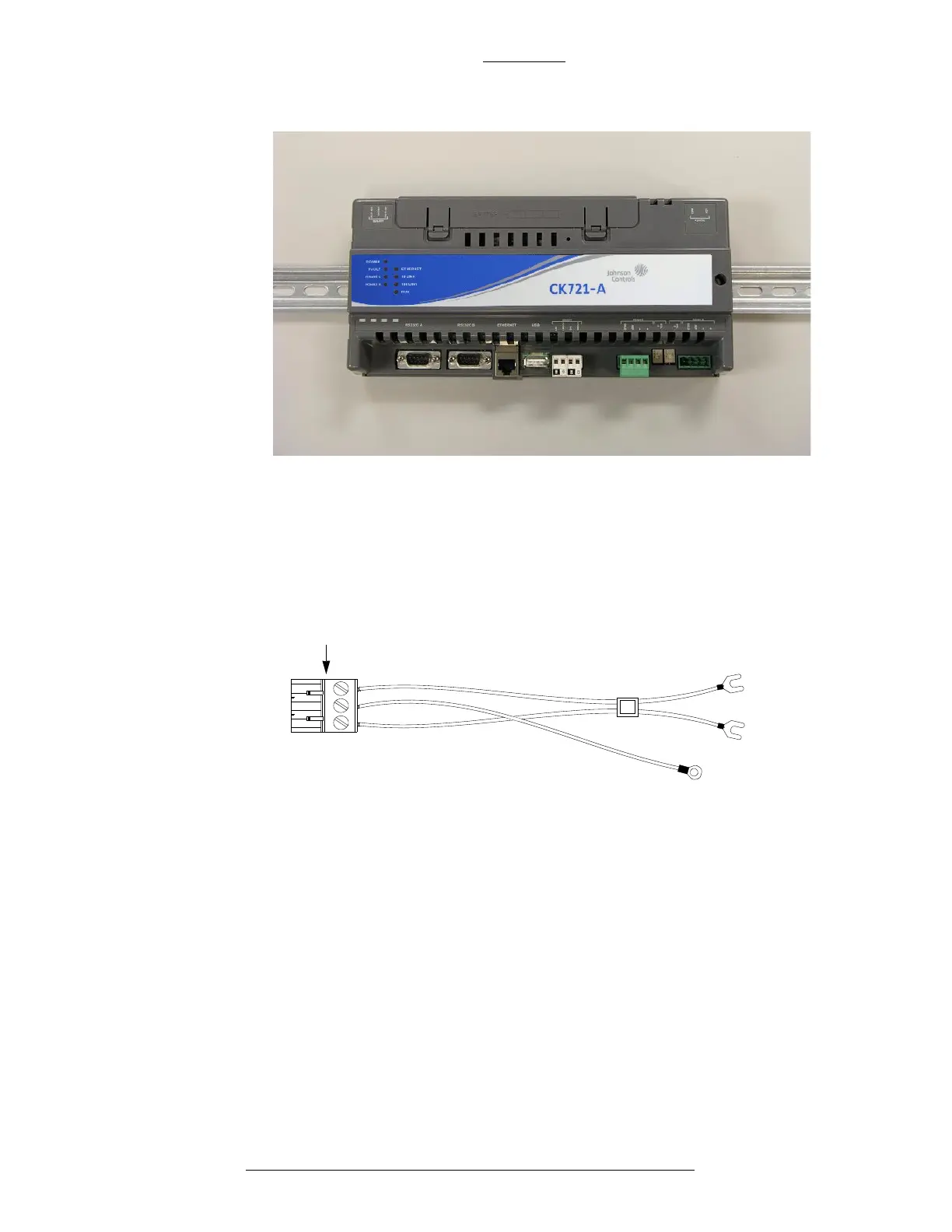
Figure 2-12: +24 VDC Connector (Part of the DC Power Harness)
CK721-A and S300-DIN Enclosures CK721-A Installation and Operation
2-16 24-10349-8 Rev. B
This document contains confidential and proprietary information of Johnson Controls, Inc.
© 2012 Johnson Controls, Inc.
+24 VDC CONNECTOR
Connects to the RDR2S or CK721 module
Chassis
ground
COM
+24 VDC
connector
b
l
a
c
k
re
d
g
r
e
e
n
Power Wiring
For power wiring with either the large or small enclosure, use the cable assembly
shown in Figure 2-12. To construct the power wiring, use 18AWG wires.
When connecting multiple CK721-A controllers or S300-DIN mod
ules, wire the
modules in parallel following the “daisy chain” pattern as shown in Figure 2-13. For
details on wiring multiple modules, refer to
the documentation provided with the
S300-DIN module.