Grounding and Connectors CK721-A Installation and Operation
C-2 24-10349-8 Rev. B
This document contains confidential and proprietary information of Johnson Controls, Inc.
© 2012 Johnson Controls, Inc.
Check that grounding points are clean and free from paint or corrosion.
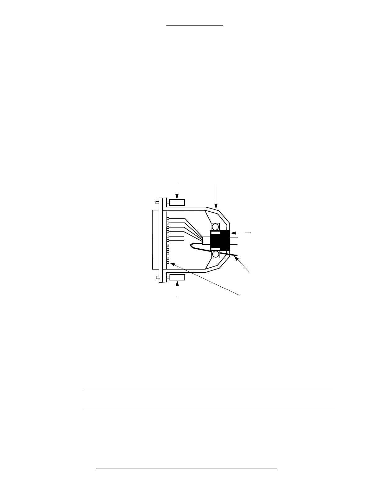
Figure C-1: Example of D-Type Connector Grounding
The two curved parts of the shroud shown in Figure C-1 make contact with the flat
plate of the shroud. Tighten the two remaining scr
ews to ensure a firm fit.
Do not remove the drain wire from the shield.
Do not connect the shield to connector pin 1 in any way.
“D-Type” Connectors
All D-type connectors must use Electromagnetic Interference (EMI) shielded
shroud. Ensure that a good contact is made when connecting D-type connector
shrouds to cable shields.
Figure C-1 shows a critical contact throughout the 360 deg
rees of the cable’s shield
at the point of entry to the shell. To ensure a good fit, strip back the cable’s ou
tside
layer to reveal the metal shield and extend the shield to the very edge of the metal
shroud’s connector. If the shield does not fit snugly, apply metallic tape to ensure a
firm contact.
Metal or metallized
connector shroud
Rubber bushing
Do not connect
cable shield to pin 1
Ensure that screws are
tight so the metal pieces
of the shroud are joined
securely here
Retaining
screws (2)
Cable shield pigtail
brought through
connector shroud
IMPORTANT