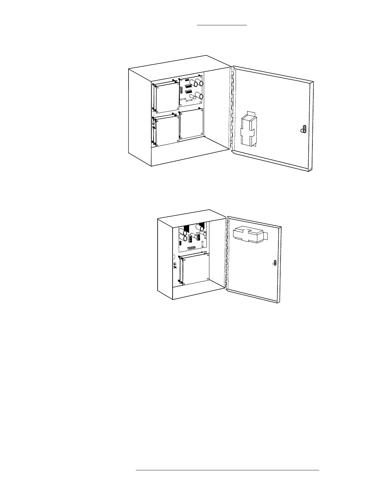
Home
Johnson Controls
Controller
CK721-A
Johnson Controls CK721-A User Manual
4
of 1
of 1 rating
234 pages
Give review
Manual
Specs
To Next Page
To Next Page
To Previous Page
To Previous Page
Loading...
Figur
e 3-13: Stacked Module Locations in S300-XXS
Figur
e 3-12: Stacked module Locations in S300-XS
2
CK721-A Installation and Oper
atio
n
S300 Expansion Enclosure
s
24-10349-8 Rev. B
3-11
This document
contains confidential and p
roprietary information
of Johnson Controls, Inc.
ï€
© 2012 Jo
hnson Cont
rols, Inc
.
4
5
60
62
Table of Contents
Default Chapter
7
Table of Contents
7
1 : Introduction
17
Manual Conventions
17
Key Terms
18
Unpacking the Equipment
19
General Description
20
CK721-A Module
20
Enclosures
21
Modules
22
Hardware Modules
22
Additional Equipment
23
Specifications (All Panels)
24
CK721-A Panel Configuration
25
Expanded Address S300 Bus Configuration
25
Legacy Address S300 Bus Configuration
25
System Configuration Example
26
Maximum Enclosure Distance
26
10/100Base-T Networking Guidelines (Specific to the CK721-A)
26
Ck721-A
26
Network Communication
27
Tcp/Ip
28
Addressing
28
10/100Base-T Ethernet
28
Communication Modes
29
CK721-A/P2000 Server Encrypted Communications
29
CK721-A/P2000 Server Encrypted Communications
30
2 : CK721-A and S300-DIN Enclosures
33
Ck721-A
33
Leds on the CK721-A
34
Binary Output
35
Setting the End-Of-Line Switch
35
Lithium Battery
36
Input Power
37
Rs485
37
Binary Input
38
Wiring between RS485B and RDR2S Module
38
Wiring between RS485B and S300 I/O Module
38
Connecting the Network
39
Hub to CK721-A Wiring
39
Rs232
39
RS232 Serial Null Modem Cable Wiring
40
Large Enclosure (S300-DIN-L)
41
Large Enclosure with Installed Components
42
One CK721-A Module and Two RDR2S Modules Mounted in a Large Enclosure
42
One CK721-A Module Mounted in a Large Enclosure
42
Wiring CK721-A and Modules
43
CK721-A Cable Requirements
43
Chain Module Wiring
44
Cable Routing
44
Chassis Grounding
45
Small Enclosure (S300-DIN-S)
45
Small Enclosure with Installed Components
45
Installing CK721-A Module
46
One CK721-A Module Mounted in a Small Enclosure
46
Cable Routing
47
Chassis Grounding
47
Verifying DC and Chassis Ground
46
No Enclosure
47
DIN Rail Mounting
47
VDC Connector
48
Power Wiring
48
Ground Wiring
49
3 : S300 Expansion Enclosures
51
Installing the Expansion Enclosures
51
Tools Required
52
Sequence of Steps
52
Planning the Installation
52
S300-XL (S300 Expansion Enclosure, Large)
53
S300-XS (S300 Expansion Enclosure, Small)
54
S300-XXS (S300 Expansion Enclosure, Extra Small)
54
S300-Xs
54
S300-Xxs
54
Removing the Knockouts
55
S300 Expansion Enclosure Knockouts
55
Mounting the Enclosures
56
Removing Boards from the Panels
56
Panel Location Suggestions
56
Mounting the Panels: S300-XL
56
Installing the Power Supplies
57
Installing the First Level Modules
57
Mounting the Panels: S300-XS
57
Mounting the Panels: S300-XXS
57
First Level Module Locations in S300-XL
58
First Level Module Locations in S300-XS
59
First Level Module Location in S300-XXS
59
Installing the Second Level (Stacked) Modules
60
Stacked Module Locations in S300-XL
60
Stacked Module Locations in S300-XS
61
Stacked Module Locations in S300-XXS
61
Cabling
62
Cable Types
62
Cabling between Enclosures
63
Cable Assembly for Enclosure to Enclosure Connection
64
Cable Assembly for Enclosure to Enclosure Connection - Details
65
Equipment Grounding
66
Power
66
S300-XFMR Transformer
66
S300 Expansion Enclosure AC Power Specifications
66
S300-PS Power Supply
67
Power Supply
67
S300 Enclosure Power Consumption
69
Applying Power to the S300 Expansion Enclosure
72
Legacy Reader Module
73
Firmware Versions for Reader Modules
73
RS-485 Wiring
73
Legacy Reader Module Firmware Versions
73
Connector Positions
74
S300-RDR2 Module
75
Reader Module Address Settings
77
Wiring Readers
78
Maximum Distance between Readers and S300 Expansion Enclosures
78
Warm-Up Resistor Removal
79
Wiring Diagram, Single Data Wire Cardkey Readers
81
Wiring Diagram, Sensor Two Data Wire Wiegand Readers
82
Wiring for Door Controls
85
Door Strike Wiring
86
Field Installed Metal Oxide Varistor
86
Auxiliary Access Switch Wiring
87
Door Open Detector Wiring
87
Shunt Relay Driver Wiring
87
Legacy I/O Modules
88
Firmware Versions for Legacy I/O Modules
88
RS-485 Wiring
88
Legacy I/O Module Firmware Versions
88
Connector Positions
89
S300-I16 Unsupervised Input Module
91
S300-I16 Module
91
S300-IO8 Unsupervised Input/Output Module
93
S300-IO8 Module
93
S300-SIO8 Supervised Input/Output Module
95
S300-SIO8 Module
95
S300-SI8 Supervised Alarm Input Module
97
S300-SI8 Module
97
Wiring Input/Output Devices
98
Expansion Enclosure Tamper Switch Wiring
98
Unsupervised Alarm Inputs
98
Supervised Alarm Inputs
100
Four-State Alarm Inputs
100
Calibrating Four-State Alarm Inputs
101
Four-State Alarm Conditions
101
Output Relay Wiring
102
Output Wiring
103
Field Installed Metal Oxide Varistor
103
Backup Battery
104
S300-BAT Battery
104
S300-BRK2 Battery Bracket Kit
105
Installing the Backup Battery
105
Battery Mounting for S300-XL and S300-XXS
106
Battery Mounting for S300-XS
106
Battery Installation Location in S300-XL
107
Battery Installation Location in S300-XS
107
Battery Installation Location in S300-XXS
108
4 : CK721-A User Interface
109
Important Notes
109
Notes on Encryption
110
Principle of Operation
110
Communicating with the User Interface
111
Using Your Terminal Emulation
111
CK721-A Controller/P2000 Host Connection Methods
111
Navigating through the User Interface
112
Write Flash
114
Clearing Database
114
Clearing the Flash Memory
115
Router Configuration
115
Notes on Adding IP Addresses in Route Configuration Screen
116
Troubleshooting
116
CK721-A Static Route Examples
117
Log out
117
Rebooting the Panel
117
Panel Menu
118
Legacy Panel Menu
118
Panel
119
Direct Programming of the CK721-A
120
Panel Screen Description
121
Panel Screen
121
Panel Screen
123
Panel Screen
125
Terminal
127
Terminal Screen
128
Terminal Screen
131
Terminal Screen
132
Terminal Screen
138
Terminal Screen
139
Offline Access Card Type Requirements
141
RDR8S Input Point and Output Point Disassociation
141
RDR2S-A Input Point and Output Point Disassociation
143
Configuring PIN Codes
144
PIN Only
144
PIN + Card ID
144
Pin
145
Four-Digit Pins
145
PIN Duress
145
PIN Plus 1 Duress
146
PIN Retry Alarm
146
Assisted Access
146
ADA Relay
147
Panel Entry/Exit
147
Badge Entry/Exit Options
147
Assisted Access Timing Diagram
147
Elevator Access Control
149
General Overview
149
Standard Low Level Interface
149
D620-ECG Low Level Interface
150
KONE HLI/KONE ELINK High Level Interface
151
KONE IP High Level Interface
152
KONE IP Elevator Support
152
KONE KIC Controller with Multiple Elevator Groups
153
And Multiple CK721-A Controllers
154
OTIS E.M.S. - Security / B.M.S. Protocol High Level Interface
155
OTIS Compass High Level Interface
158
Basic Definitions
160
Performance Considerations
161
Cabinet Access Control
161
Elevator or Cabinet Terminal
162
Elevator or Cabinet Terminal Screen
165
Elevator or Cabinet Terminal Screen, Pages 6 and 7
165
Output
166
Output Screen
167
Holiday
168
Access Group
169
Holiday Screen
169
Elevator Access Group
170
Elevator Access Group Screen
170
Control Door
171
Panel Soft Alarm
172
Panel Soft Alarm
173
Password Change
174
Reboot
174
Badge
175
Badge Screen
177
Badge Screen
178
Input
179
Input Screen
181
Time Zone
183
Card Events
184
Card Event Screen
186
Card Event Screen
187
System Information
189
System Information Screen
189
System Information Screen
191
Control Output
192
Change Date
193
5 : Maintenance
195
Routine Maintenance
195
Impaired Performance Conditions
195
Troubleshooting Guidelines
195
Testing Procedure
196
Check Backup Battery Operation
196
Lithium Battery Replacement
196
Field Servicing
197
Troubleshooting
197
Appendix A: Expanded Address S300 Bus
199
Appendix B: Performance Analysis
202
Appendix C: Grounding and Connectors
203
Cable Grounding
203
D-Type" Connectors
204
Non "D-Type" Grounding Connections
205
Installations in the USA
205
Example of Grounding Shielded Cable at both Ends
205
Installations in Europe
206
Card Reader Unit Grounding
206
Example of Grounding Shielded Cable at Only One End
206
Appendix D: Door Open/Aux Access Supervision
207
Purpose of Supervised Inputs
207
Appendix E: Database Flash Backup from the Host
212
Appendix F: Using a Keypad Reader on a Panel
213
Invoking Access Requests from a Keypad
213
Invoking Air Crew Access Requests from a Keypad
214
Invoking Timed Overrides from a Keypad
214
Invoking Panel Card Events from a Keypad
217
Quick Guide to Using Keypad Readers
220
Appendix G: Configuring SSH and SFTP Clients
225
Putty Client
225
Winscp Client
229
Other manuals for Johnson Controls CK721-A
Factory Field Upgrade
22 pages
Upgrade Manual
20 pages
Hardware Installation Manual
19 pages
Factory Field Installation
21 pages
4
Based on 1 rating
Ask a question
Give review
Questions and Answers:
Need help?
Do you have a question about the Johnson Controls CK721-A and is the answer not in the manual?
Ask a question
Johnson Controls CK721-A Specifications
General
Brand
Johnson Controls
Model
CK721-A
Category
Controller
Language
English
Related product manuals
Johnson Controls CGM09090
24 pages
Johnson Controls CGM04060
24 pages
Johnson Controls M4-CVM03050
24 pages
Johnson Controls M4-CGM09090
26 pages
Johnson Controls F4-CG Series
28 pages
Johnson Controls F4-CV Series
22 pages
Johnson Controls M4-CG Series
24 pages
Johnson Controls F4-CGM04060-0
28 pages
Johnson Controls F4-CVM03050-0
36 pages
Johnson Controls M4-CGM Series
26 pages
Johnson Controls F4-CGM09090-0H
28 pages
Johnson Controls F4-CGE09090-0H
28 pages