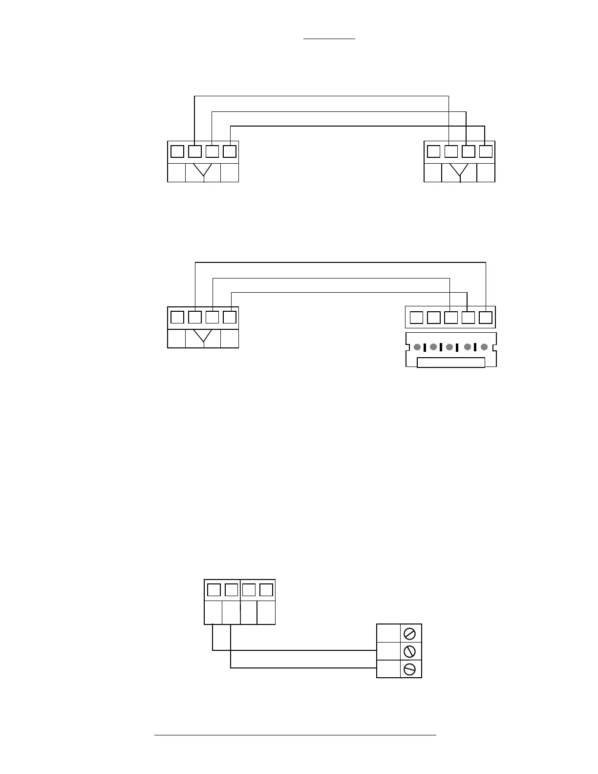
Figure 2-2: Wiring Between RS485B and S300 I/O Module
Figure 2-3: Wiring Between Binary Input 1 and Trouble Pin
Figure 2-1: Wiring Between RS485B and RDR2S Module
A
SH
LD
-
+
REF
CK721-A
S300 I/O
REF
-
+
A
SH
LD
-
+
REF
A
SH
LD
-
+
REF
REF
-
+
CK721-A
RDR2S
CK721-A and S300-DIN Enclosures CK721-A Installation and Operation
2-6 24-10349-8 Rev. B
This document contains confidential and proprietary information of Johnson Controls, Inc.
© 2012 Johnson Controls, Inc.
Binary Input
CK721-A has two Binary Inputs:
Binary Input 1
This input is logically mapped at the host as the soft
alarm Panel Lost AC.
The Binary Input 1 is wired to the Trouble pin lo
cated on the power supply.
The Trouble pin is activated when there is no AC power and the battery
voltage drops to 23.9 VDC or less. For wiring details see Figure 2-3.
NO C
CK721-A: BINARY
COM2
IN2
COM1
IN1
NC
Power Supply:
TROUBLE