Introduction CK721-A Installation and Operation
1-10 24-10349-8 Rev. B
This document contains confidential and proprietary information of Johnson Controls, Inc.
© 2012 Johnson Controls, Inc.
System Configuration Example
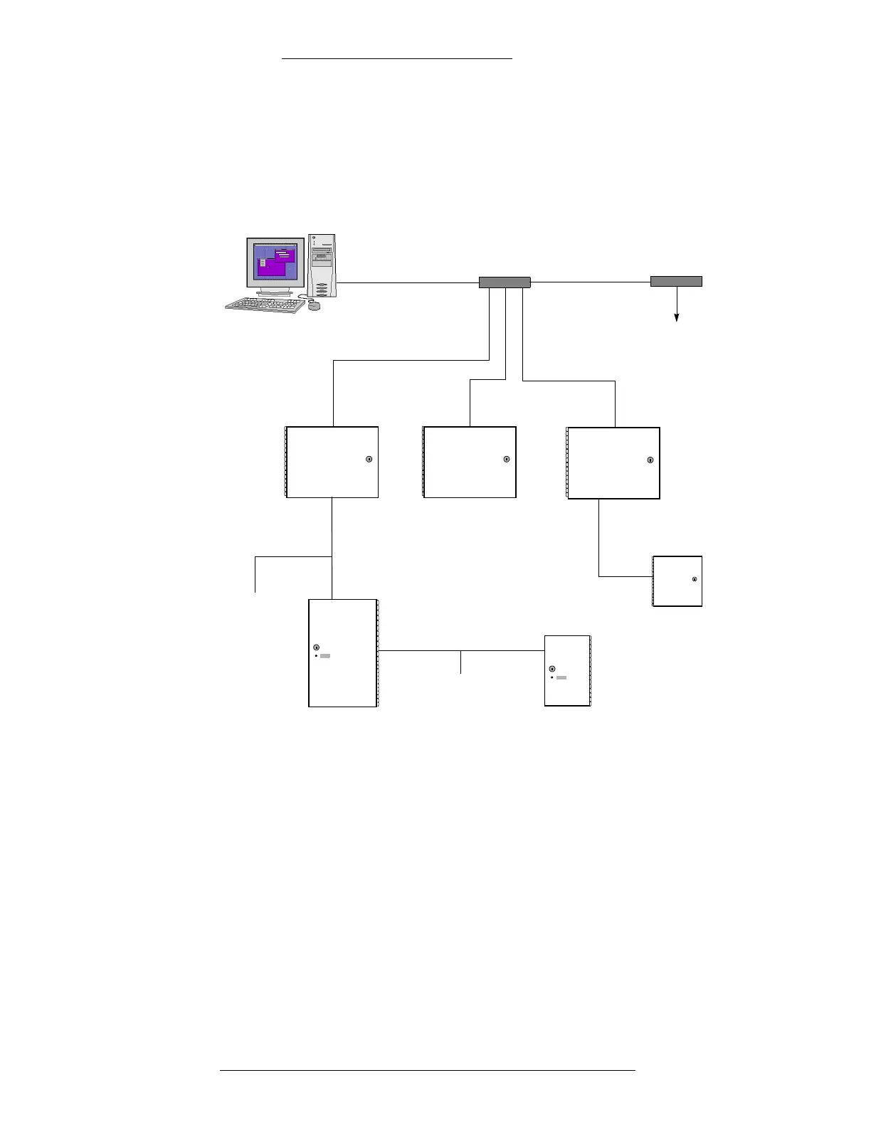
Figure 1-1 illustrates a simple CK721-A system configuration. For more
information on panel installation and network connectivity, see Chapter 3: S300
Expansion Enclosures and Chapter 4: CK721-A User Interface.
Figure 1-1: Sample CK721-A System Configuration
P2000 Server
10/100Base-T Hub
RS-485
RS-485
S300-XS
S300-XL
S300-DIN-S
RS-485
S300-DIN-L
(Note that while S300-DIN-L
10/100Base-T Hub
To additional CK721-As
or hubs
Last terminal in S300-XL
connected to the
terminal in S300-XS.
CK721-A or last
terminal in
S300-DIN-L
connected to
the first terminal
in the expansion
enclosure.
expansion enclosures are
shown, S300-DIN-S could
also be used.)
CK721-A CK721-A CK721-A
Maximum Enclosure Distance
CK721-A communicates with the P2000 server via a 10/100Base-T Ethernet and
TCP/IP protocol, therefore cabling of the system needs to comply with the
industry-standard network guidelines.
10/100Base-T Networking Guidelines (specific to the CK721-A)
As a network device, the CK721-A can be installed in a variety of configurations
based on the needs of your sites. The CK721-A communicates with the P2000 server
through one or more 10/100Base-T hubs.