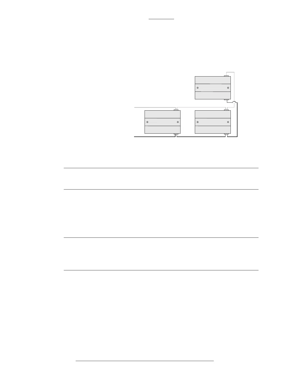
Figure 2-8: Daisy Chain Module Wiring for S300-DIN-L
Do not connect the DC power cable to the reader unit until all wiring is
complete.
CK721-A and S300-DIN Enclosures CK721-A Installation and Operation
2-12 24-10349-8 Rev. B
This document contains confidential and proprietary information of Johnson Controls, Inc.
© 2012 Johnson Controls, Inc.
Chain Module Wiring
When connecting more than one module, wire the modules in parallel following the
“daisy chain” pattern, as shown in Figure 2-8. For wiring details refer to the
documentation provided with the S300-DIN module.
3nd Module
1st Module 2nd Module
DC power cable
connecting to
power supply
RS-485 cable
IMPORTANT
Cable Routing
All low-level input cables, such as system data and reader cables, must be shielded
types. The cables should run in grounded conduit or at least two feet from AC
power, fluorescent lights, or other high energy sources.
IMPORTANT
All data cables should be physically separated from power lines. If conduit
is used, do not run data cables in the same conduit as power cables or
certain door strike cables, e.g. strike voltage greater that 42V or Magnetic
door locks without EMI suppression.
All cables must conform with National Electrical Code, NFPA 70,* and local
electrical codes. Cabling should be made using good wiring practices and should be
long enough to allow service loops at their terminations in the enclosure. *For
Canadian installations, refer to the Canadian Electric Code C22.1.
Grounding Cable Shields
Refer to Appendix C: Grounding and Connectors for details on the requirements.
The grounding screws used are #6 x 1/4” self-tapping
, and are provided in the
hardware installation kit.