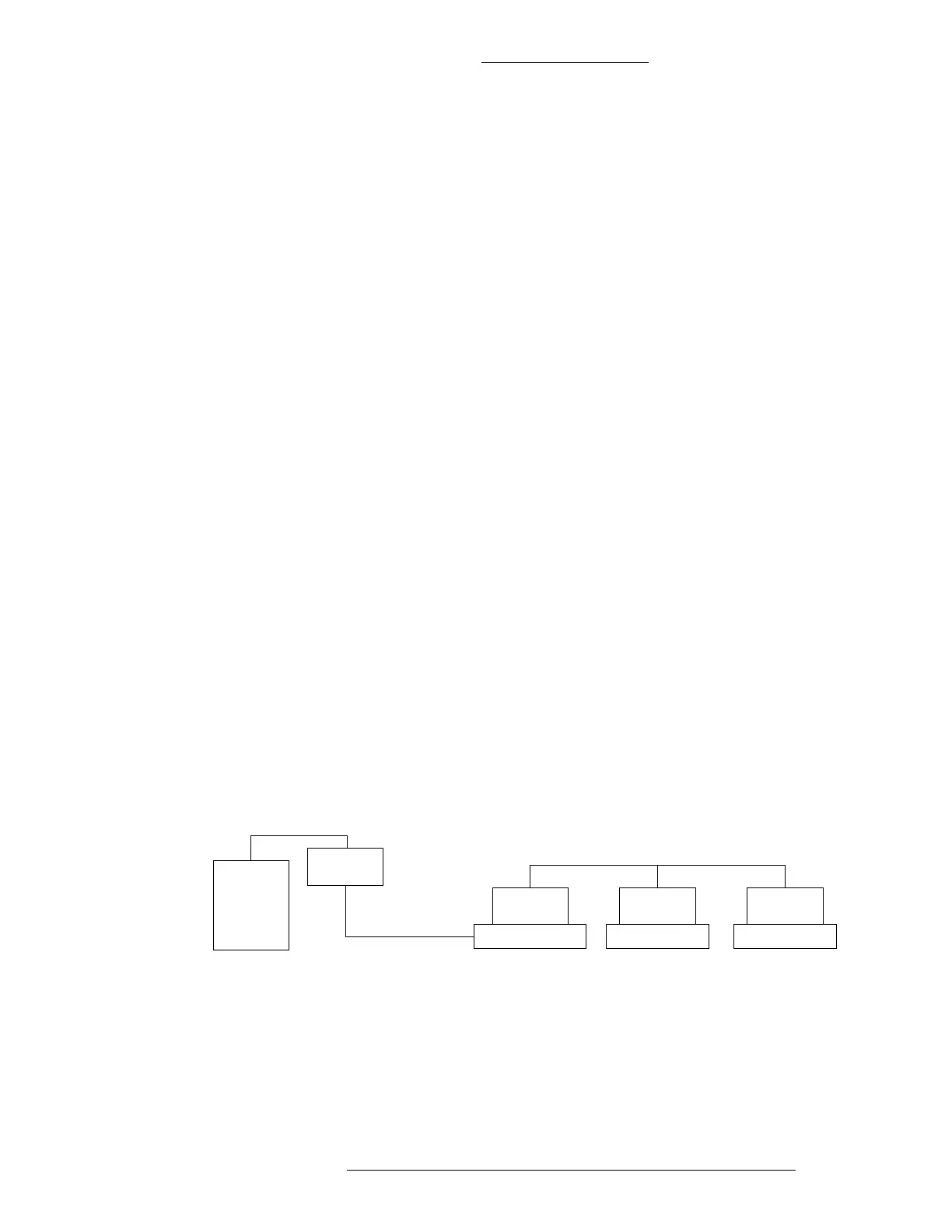
Figure 4-7: Master-Slave Elevator Configuration Layout
CK721-A Installation and Operation CK721-A User Interface
24-10349-8 Rev. B 4-47
This document contains confidential and proprietary information of Johnson Controls, Inc.
© 2012 Johnson Controls, Inc.
OTIS E.M.S. - Security / B.M.S. Protocol High Level Interface
The OTIS Elevator Management System (EMS) controls up to 8 groups of elevators,
with each group consisting of up to 8 elevators. It interfaces to the Building
Management System (BMS) through an RS422 interface. As the current CK721-A
controller supports up to 16 elevator readers, multiple CK721-A may need to be
connected to control access to all elevators managed by the EMS.
The number of elevators, and their assignment to elevator
g
roups determines the
number of CK721-A controllers required. All elevators of each single group must be
handled by the same CK721-A. Each CK721-A can support multiple groups, as long
as the total number of elevators in these groups does not exceed 16.
One CK721-A controller needs to be designated the OTIS master.
The
master
CK721-A controller RS-232C serial B port (3 wire full duplex RS232 interface) is
connected to an RS232 to RS422 converter, which is connected to the OTIS EMS
(4 wire full duplex RS422 interface).
The recommended module is 485TBLED converter from B & B Electron
ics or
its
equivalent.
For this model both the CONTROL and the ECHO ju
mpers need to be completely
removed to act as an RS232 to RS422 converter.
The 485TBLED is connected to the CK721-A master with a 3 wire interface,
consisting of pins 2, 3
and 7.
The 485TBLED is connected to the OTIS EMS with a 4 wire interface:
OTIS EMS's TDA(-) to Converter's RDA(-)
OTIS EMS's TDB(+) to Converter's RDB(+)
OTIS EMS's RDA(-) to Converter's TDA(-)
OTIS EMS's RDB(+-)to Converter's TDB(+)
Proper shielding and grounding may be required.
3-wire half duplex RS485
RS-422
RS-232
RS485A
Serial Port
CK721-A Master
RS485A
Serial Port
CK721-A Slave
RS485A
Serial Port
CK721-A Slave
4-wire full duplex RS422
3-wire full duplex RS232
OTIS
EMS
RS-232C B
Serial Port