CK721-A Installation and Operation CK721-A and S300-DIN Enclosures
24-10349-8 Rev. B 2-7
This document contains confidential and proprietary information of Johnson Controls, Inc.
© 2012 Johnson Controls, Inc.
Binary Input 2
This input is logically mapped at the host as the soft
alarm Panel Tamper.
The open state means “alarm set,” and the close
d state means “alarm secure.”
Connecting the Network
The CK721-A system communicates with the P2000 server via 10/100Base-T
Ethernet, using the TCP/IP protocol.
The following types of wiring may be required:
Hub to CK721-A, straight through
Hub to hub straight-through or crossed, depending on the hub used
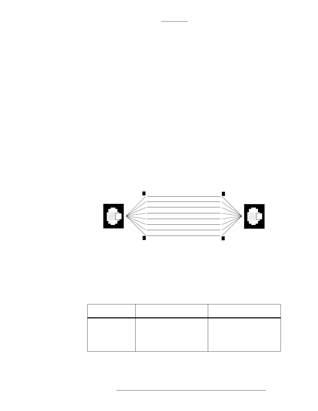
Figure 2-4: Hub to CK721-A Wiring
Hub to CK721-A Wiring
All network devices designed for 10/100Base-T networking use standard RJ45, 8
pin ports. Like other 10/100Base-T devices, the CK721-A RJ45 port is designed to
connect to a hub using pins 1, 2, 3, and 6, wired straight through.
NC
NC
RXD-
NC
NC
RxD+
TxD-
TxD+
8
1
NC
Output Transmit Data -
NC
NC
Output Transmit Data +
Input Receive Data -
Input Receive Data+
8
1
NC
CK721-A
HUB
RS232
CK721-A has two RS232 connectors: RS232C A and RS232C B.
Table 2-3: RS232 Connectors
Description RS232C A RS232C B
Port use Connects to a terminal
em
ulator
Dual use. Connects to either:
Data logger device
KONE elevator controller
interface