CK721-A and S300-DIN Enclosures CK721-A Installation and Operation
2-14 24-10349-8 Rev. B
This document contains confidential and proprietary information of Johnson Controls, Inc.
© 2012 Johnson Controls, Inc.
Verifying DC and Chassis Ground
To verify DC ground:
1. Verify the wire connection between the power supply and COM on the
hardware module.
2. Verify the wire connection between the power supply and its standoff.
To verify chassis ground:
1.
Verify the wire connection between the hardware modu
le’s earth and the
backplate.
2. Verify the wire connection between the AC power source and the backplate.
3. Verify the wire connection between the DC-
and one of th
e power supply’s
mounting holes.
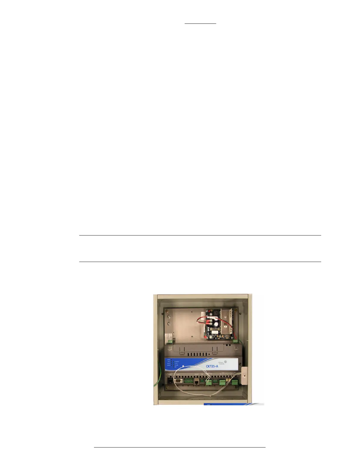
Figure 2-10: One CK721-A Module Mounted in a Small Enclosure
Installing CK721-A Module
The CK721-A module is mounted on a backplate’s DIN rail.
To mount a module, align it with the rail and snap on. To remove a module, pull
down the white clip located on the bottom of th
e module, then pull the bottom of the
module out and lift it up.
NOTE
Do not connect the DC power cable to the CK721-A until all wiring is
complete.
The following figure depicts one CK721-A module in a small enclosure.