CK721-A Installation and Operation S300 Expansion Enclosures
24-10349-8 Rev. B 3-39
This document contains confidential and proprietary information of Johnson Controls, Inc.
© 2012 Johnson Controls, Inc.
IMPORTANT
Observe the following precautions:
Ensure that the notch on the RS-485 cable faces the lip on the module’s
connector. Plugging the cable in backwards may damage the module.
Do not remove or connect the RS-485 connectors before powering down the
S300 expansion enclosure.
NOTE
It is difficult to set the switches of the first level modules and connect the
RS-485 cables once the stacked modules are installed.
Each module is shipped with an RS-485 cable. The first module connects the cable
between J5 on the CK721-A and one of the RS-485 connectors listed in Table 3-17
depending on which module is installed.
Additional modules are connected
in daisy-chain fashion. For example, using the
supplied cable shipped with a second module, connect the unused RS-485 on the
first module, and then connect the other end to a RS-485 interface on the second
module.
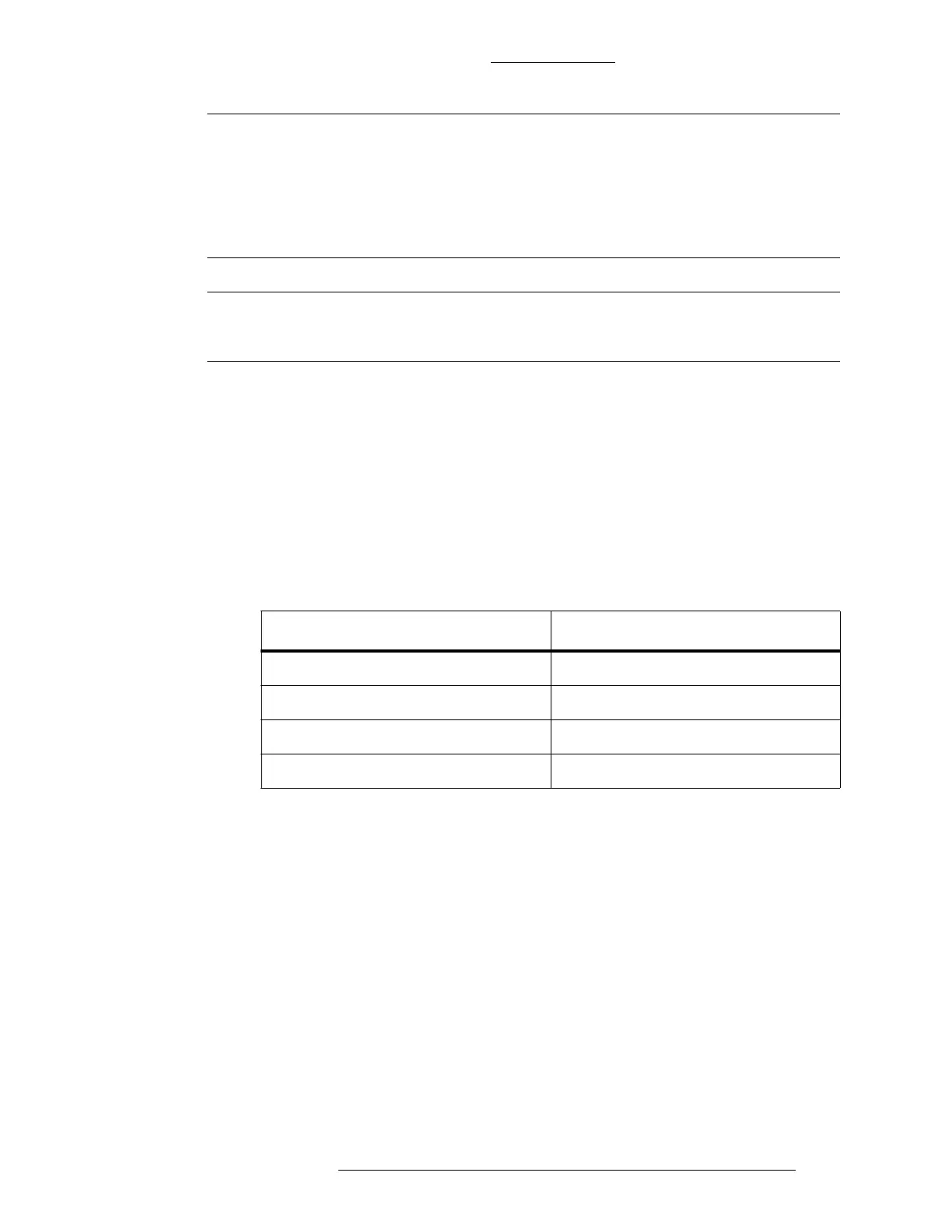
Table 3-17: RS-485 Connector Positions
Modules Connector Positions
I16 Input Module J2, J3
IO8 I/O Module J3, J4
SIO8 I/O Module J3, J4
SI8 Input Module J3, J4
No two I/O modules connected to the same CK721-A can have the same address.
Addresses are set by switches located on the modules. Table 3-18 shows the proper
switch settings for each address.