CK721-A User Interface CK721-A Installation and Operation
4-54 24-10349-8 Rev. B
This document contains confidential and proprietary information of Johnson Controls, Inc.
© 2012 Johnson Controls, Inc.
Elevator or Cabinet Terminal
To display an elevator’s or cabinet’s configuration, select the terminal assigned to
the elevator or cabinet by number or select <Previous Record> or <Next Record>.
The following screens are then added to the base four screens used to display a
terminal.
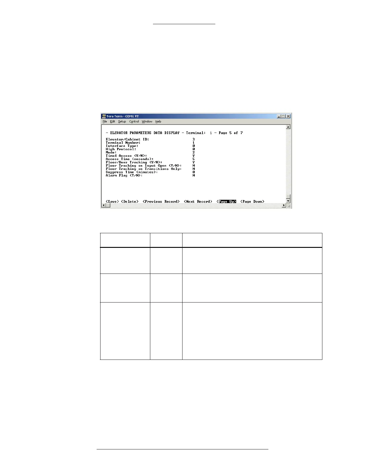
Elevator or Cabinet Terminal Screen - Page 5
Table 4-12: Elevator or Cabinet Terminal Screen, Page 5
Field Type Description
Elevator/
Cabinet ID
User Def. A numeric value that identifies the elevator or
ca
binet to the system. This value is assigned by
the server and cannot be edited by the user.
Termin a l
Number
U
ser Def. A read-only field that identifies the terminal
associated with this elevator or cabinet.
Value range: 1 to 16.
Interface Type User Def. A read-only field that identifies the type of elevator
or
cabinet control in use:
0 = low level interface
1 = high level interface (RS232)
The following high level interfaces are supported:
KONE PLC-
HLI/KONE ELINK, OTIS BMS, OTIS
COMPASS, and KONE IP.